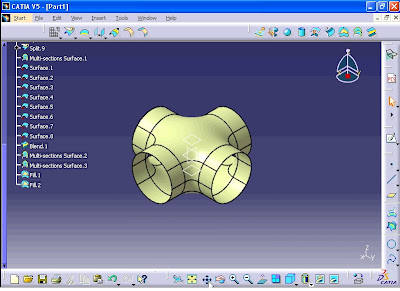
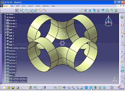
The aim of the exercise is to create a model as shown in the figure.
From menu click Start - Mechanical Design - Wireframe and Surface Design.

From menu click Start - Mechanical Design - Wireframe and Surface Design.

New Part window opens. Click on OK.

From menu click on Insert - Geometrical Set.

'Insert Geometrical Set' window opens. Enter set-01 in Name box and click OK.

Now click on Sketch button.

Click on yz plane from tree.

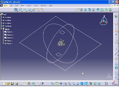
Then create a circle which its center is the origin of the coordinate system. By using Constraint command define the diameter of the circle.

The radius constraint appears on the circle double click on the constraint.

Constraint Definition window opens. Enter 60 mm in Diameter box and click OK.

Now exit the sketch workbench.

Again click on sketch command and select zx plane from tree.

Again create a circle with center of origin and diameter of 60 mm.

Now exit the sketch workbench.

Again click on sketch command and click on xy plane from tree.

Click on Centered Rectangle command.
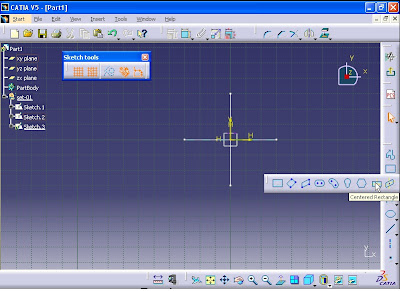
Create a rectangle which its center is the origin and length of each side is 80 mm.

Exit the Sketch workbench.

Now click on Plane from Wireframe toolbar. Plane Definition window opens. From Plane type list select 'Offset from plane' option.

Click on xy plane. Then enter 20 mm in Offset box.
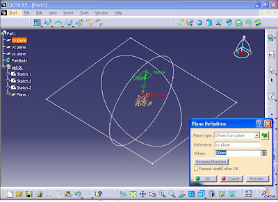
Click on OK.
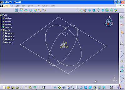
Again click on Plane command. Plane Definition window opens. Click on xy plane. This time click on Reverse Direction button. The plane is created at the other side of the xy plane with offset of 20 mm.
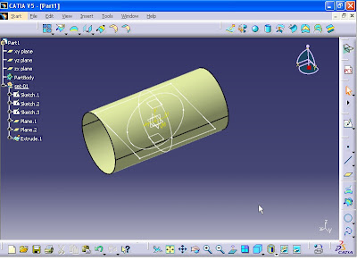
Now click on Extrude from Surfaces toolbar. Extruded Surface Definition window opens. Select the first circle.

Enter 60 mm in Dimension boxes for Limit 1 and Limit 2. Then click on Preview.

Click on OK.
Again click on Extrude command. Extruded Surface Definition window opens. Click on the second circle. Enter 60 mm in Dimension boxes for Limit 1 and Limit 2 and click on OK.
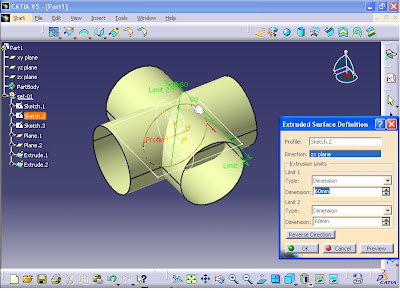
For last time click on Extrude command. On Profile, click on the rectangle. Enter 60 mm in Dimension boxes for Limit 1 and Limit 2 and click on OK.

On Extrude.3 from tree, right click and select Properties.
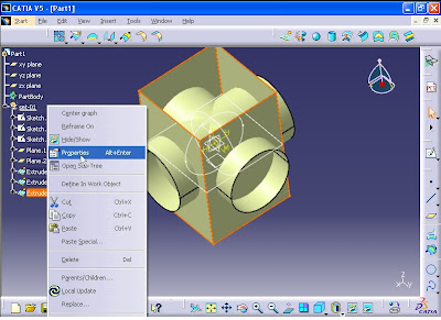
In Properties window, click on Graphic tab. Then click on Color list and select a color.

Then click on OK.
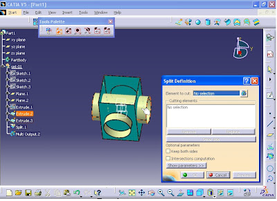
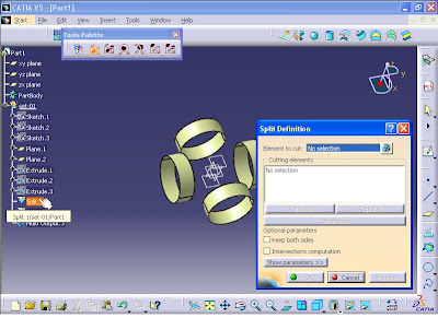
From Operations toolbar, click on Split command. Split Definition window opens. For Element to cut, click on Extrude.1.

For Cutting elements section, click on Extrude.3.

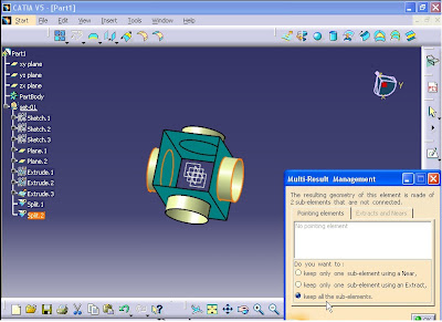
Now click on OK. Multi-Result Management window opens. Select 'Keep all the sub-elements' option.

Click on OK.

Again repeat Split command from Operations toolbar. Then for Element to cut section click on Extrude.2.
For Cutting elements click on Extrude.3.

Now click on OK. Multi-Result Management window opens. Select 'Keep all the sub-elements' option.
Click on OK.

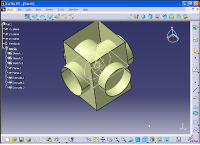
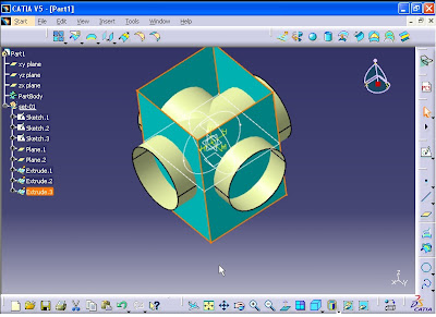
From tree, click on Extrude.3 and right click on it. Then select Hide/Show option to hide the extruded rectangle.

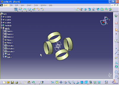
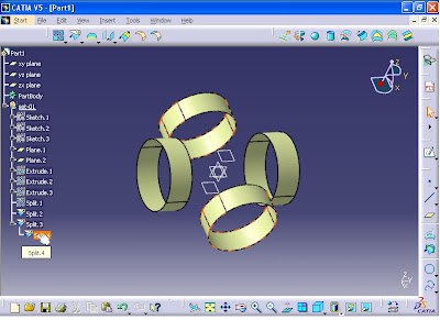
Now the model looks like the image below.
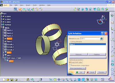
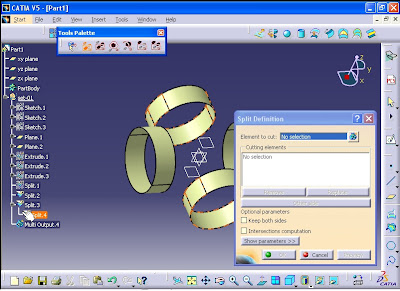
In next step, the cylinder surfaces are split into separate surfaces. Again click on Split command from Surfaces toolbar. For Element to cut, click on Split.1.
For Cutting elements, click on Plane.1.

Then select Keep both sides option. Then click on OK.
Multi-Result Management window opens. Select 'Keep all the sub-elements' option and click OK.
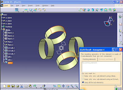
Now two new elements of Split.3 and Split.4 are added to the tree.
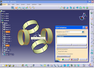
Again click on Split command. For Element to cut, click on Split.4.
For Cutting elements, click on Plane.2. Then select 'Keep both sides' option and click OK.

Multi-Result Management window opens. Select 'Keep all the sub-elements' option and click on OK.

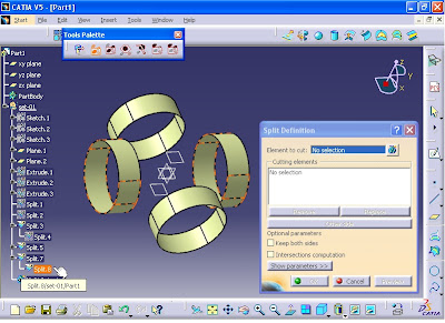
Repeat all the above procedures for the other two rings. Click on Split from Operations toolbar. For Element to cut, click on Split.2.

For Cutting elements, click on Plane.1. Select 'Keep both sides' option and click on OK.
Multi-Result Management window opens. Select 'Keep all the sub-elements' option and click on OK.

Again click on Split command. For Element to cut, click on Split.8.
For Cutting elements, click on Plane.2. Then select 'Keep both sides' option and click OK.

Multi-Result Management window opens. Select 'Keep all the sub-elements' option and click on OK.

Next, click on Multi-Sections Surface command. Multi-Sections Surface Definition window opens.

For Section, Select the edges as shown in the following figures.

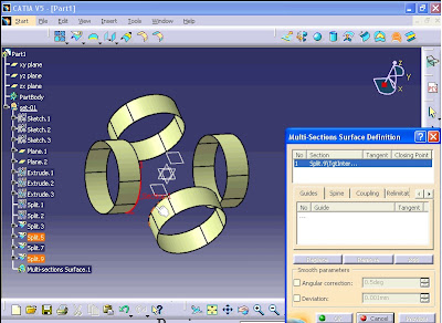
Make sure that the direction of the arrows are in correct direction then click on Preview.

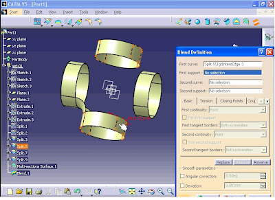
Click on OK. Now This time the Blend command is used to compare it with the previous command (Multi-Sections Surface command). Click on Blend command from Surfaces toolbar. For First curve section click on the edge as shown in the figure.

For 'First support' section, click on the surface as shown in the figure.
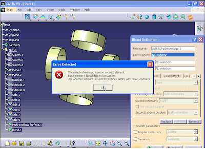
An error message box appears. Because all the Split.5 surface is selected. Click on OK to close the window.
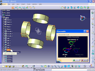
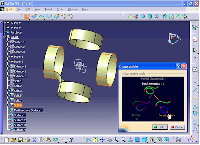
To solve the problem, first cancel the Blend command. Then click on Disassemble command from Operations toolbar. Disassemble window opens. Then select Split.5 surface.

Then from window click on 'Domains only' option. Click on OK.

The result: 4 separate surfaces are created.

Repeat the procedure for Split.9. Click on Disassemble command from Operations toolbar. Disassemble window opens. Then select Split.9 surface.
Then from window click on 'Domains only' option. Click on OK.
The result is: 4 separate surfaces are created.

Now we can use Blend command. From Operations toolbar, click on Blend command. Blend Definition window opens. For First curve section, click on the edge as shown in the figure.
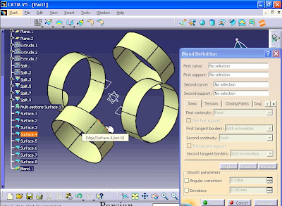
For First support section, click on the adjacent surface to the edge.

Then for Second curve section, click on the edge as shown in the figure.

For Second support section, click on the adjacent surface to the edge. Make sure that the direction of the arrows are correct.

Then click on OK.

As you see the result of surface created by Blend command is exactly the same the surface created by Multi-Sections surface command.
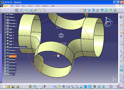
Next, click on Multi-Sections surface command. Multi-Sections Surface Definition window opens. For Section, click on the edge as shown in the figure.

Then select the other edge as shown in the figure.

Make sure that the directions of the arrows are in the same direction. Then click on OK.
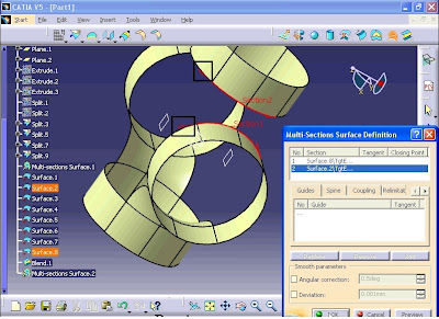

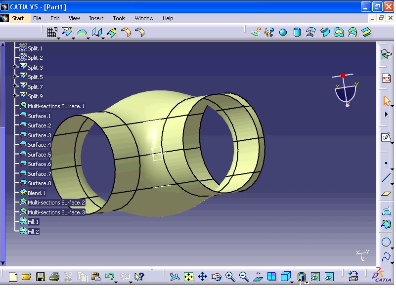
Repeat Multi-Sections surface command. Multi-Sections Surface Definition window opens. For Section, click on the edge as shown in the figure.

Then select the other edge as shown in the figure.

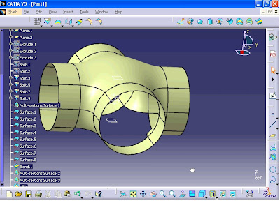
Then click on OK. Now the model looks like the image below.
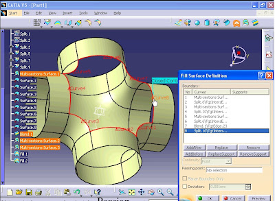
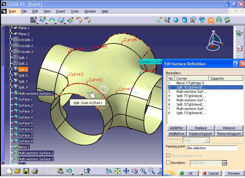
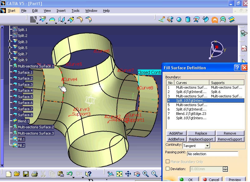
Now in next stage, two surfaces, which covers the top and bottom section of the model are created. Now from Surfaces toolbar click on Fill command. Fill Surface Definition window opens. For Boundary section, select the top open edges as shown in the figures.

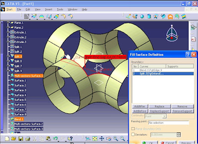


Now click on Preview.
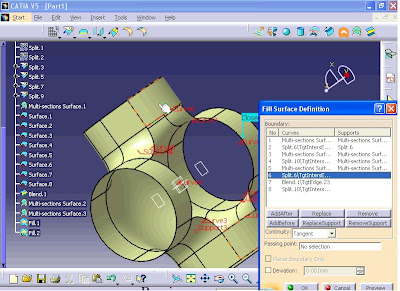
In Boundary, click on Supports section and select the adjacent surfaces to the selected surfaces as shown in the figure.


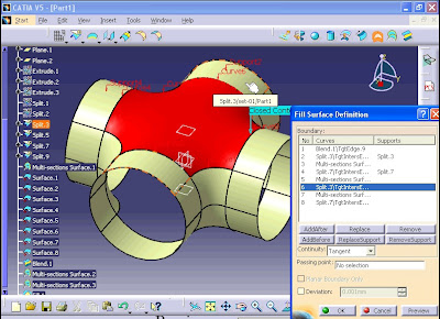
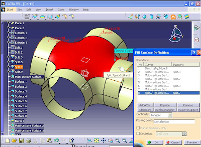
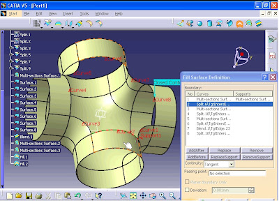
Then from Continuity list select 'Tangent' option and finally click on Preview.

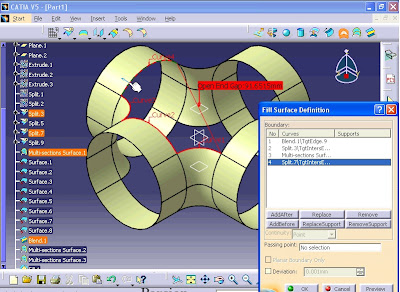
Next for Supports section click on the surfaces as shown in the figure.


Click on Preview.

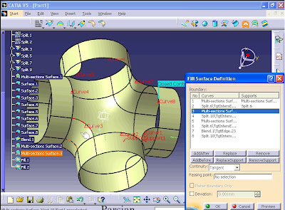
Click on OK.
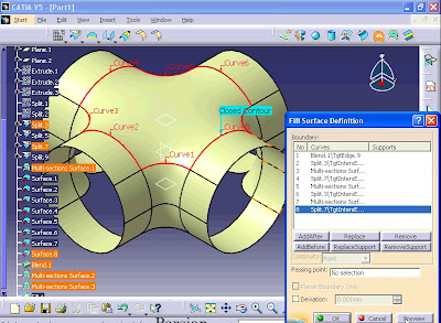
Repeat the Fill command for the bottom section of the model. Click on Fill command. Fill Surface Definition window opens. For Boundary section, click on thew edges respectively as shown in the figure.

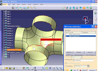

In Boundary, click on Supports section and select the adjacent surfaces to each relevant edge respectively as shown in the figure.


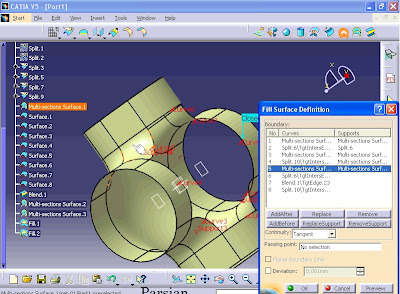
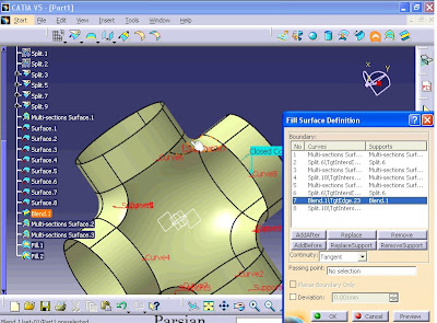

Click on Preview.

And click on OK.

In specification tree there many items. These elements, such as commands and wireframes belongs to the model. To find the name of the element from tree, right click on the element in the model and select 'Center graph' option.

Now as you see the name of the element is highlighted in the tree.

If you want to find the item from tree, select the name of the element from tree and right click on it then select 'Reframe On' option.
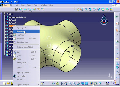
As you see the selected element is highlighted in the model.


Again create a circle with center of origin and diameter of 60 mm.

Now exit the sketch workbench.

Again click on sketch command and click on xy plane from tree.

Click on Centered Rectangle command.

Create a rectangle which its center is the origin and length of each side is 80 mm.

Exit the Sketch workbench.

Now click on Plane from Wireframe toolbar. Plane Definition window opens. From Plane type list select 'Offset from plane' option.

Click on xy plane. Then enter 20 mm in Offset box.

Click on OK.

Again click on Plane command. Plane Definition window opens. Click on xy plane. This time click on Reverse Direction button. The plane is created at the other side of the xy plane with offset of 20 mm.

Now click on Extrude from Surfaces toolbar. Extruded Surface Definition window opens. Select the first circle.

Enter 60 mm in Dimension boxes for Limit 1 and Limit 2. Then click on Preview.

Click on OK.

Again click on Extrude command. Extruded Surface Definition window opens. Click on the second circle. Enter 60 mm in Dimension boxes for Limit 1 and Limit 2 and click on OK.

For last time click on Extrude command. On Profile, click on the rectangle. Enter 60 mm in Dimension boxes for Limit 1 and Limit 2 and click on OK.


On Extrude.3 from tree, right click and select Properties.

In Properties window, click on Graphic tab. Then click on Color list and select a color.

Then click on OK.

From Operations toolbar, click on Split command. Split Definition window opens. For Element to cut, click on Extrude.1.

For Cutting elements section, click on Extrude.3.

Now click on OK. Multi-Result Management window opens. Select 'Keep all the sub-elements' option.

Click on OK.

Again repeat Split command from Operations toolbar. Then for Element to cut section click on Extrude.2.

For Cutting elements click on Extrude.3.

Now click on OK. Multi-Result Management window opens. Select 'Keep all the sub-elements' option.

Click on OK.

From tree, click on Extrude.3 and right click on it. Then select Hide/Show option to hide the extruded rectangle.

Now the model looks like the image below.

In next step, the cylinder surfaces are split into separate surfaces. Again click on Split command from Surfaces toolbar. For Element to cut, click on Split.1.

For Cutting elements, click on Plane.1.

Then select Keep both sides option. Then click on OK.

Multi-Result Management window opens. Select 'Keep all the sub-elements' option and click OK.

Now two new elements of Split.3 and Split.4 are added to the tree.

Again click on Split command. For Element to cut, click on Split.4.

For Cutting elements, click on Plane.2. Then select 'Keep both sides' option and click OK.

Multi-Result Management window opens. Select 'Keep all the sub-elements' option and click on OK.

Repeat all the above procedures for the other two rings. Click on Split from Operations toolbar. For Element to cut, click on Split.2.

For Cutting elements, click on Plane.1. Select 'Keep both sides' option and click on OK.

Multi-Result Management window opens. Select 'Keep all the sub-elements' option and click on OK.

Again click on Split command. For Element to cut, click on Split.8.

For Cutting elements, click on Plane.2. Then select 'Keep both sides' option and click OK.

Multi-Result Management window opens. Select 'Keep all the sub-elements' option and click on OK.

Next, click on Multi-Sections Surface command. Multi-Sections Surface Definition window opens.

For Section, Select the edges as shown in the following figures.


Make sure that the direction of the arrows are in correct direction then click on Preview.

Click on OK. Now This time the Blend command is used to compare it with the previous command (Multi-Sections Surface command). Click on Blend command from Surfaces toolbar. For First curve section click on the edge as shown in the figure.

For 'First support' section, click on the surface as shown in the figure.

An error message box appears. Because all the Split.5 surface is selected. Click on OK to close the window.

To solve the problem, first cancel the Blend command. Then click on Disassemble command from Operations toolbar. Disassemble window opens. Then select Split.5 surface.

Then from window click on 'Domains only' option. Click on OK.

The result: 4 separate surfaces are created.

Repeat the procedure for Split.9. Click on Disassemble command from Operations toolbar. Disassemble window opens. Then select Split.9 surface.

Then from window click on 'Domains only' option. Click on OK.

The result is: 4 separate surfaces are created.

Now we can use Blend command. From Operations toolbar, click on Blend command. Blend Definition window opens. For First curve section, click on the edge as shown in the figure.

For First support section, click on the adjacent surface to the edge.

Then for Second curve section, click on the edge as shown in the figure.

For Second support section, click on the adjacent surface to the edge. Make sure that the direction of the arrows are correct.

Then click on OK.

As you see the result of surface created by Blend command is exactly the same the surface created by Multi-Sections surface command.

Next, click on Multi-Sections surface command. Multi-Sections Surface Definition window opens. For Section, click on the edge as shown in the figure.

Then select the other edge as shown in the figure.

Make sure that the directions of the arrows are in the same direction. Then click on OK.


Repeat Multi-Sections surface command. Multi-Sections Surface Definition window opens. For Section, click on the edge as shown in the figure.

Then select the other edge as shown in the figure.

Then click on OK. Now the model looks like the image below.

Now in next stage, two surfaces, which covers the top and bottom section of the model are created. Now from Surfaces toolbar click on Fill command. Fill Surface Definition window opens. For Boundary section, select the top open edges as shown in the figures.


Now click on Preview.

In Boundary, click on Supports section and select the adjacent surfaces to the selected surfaces as shown in the figure.


Then from Continuity list select 'Tangent' option and finally click on Preview.

Next for Supports section click on the surfaces as shown in the figure.


Click on Preview.

Click on OK.

Repeat the Fill command for the bottom section of the model. Click on Fill command. Fill Surface Definition window opens. For Boundary section, click on thew edges respectively as shown in the figure.


In Boundary, click on Supports section and select the adjacent surfaces to each relevant edge respectively as shown in the figure.


Click on Preview.

And click on OK.
In specification tree there many items. These elements, such as commands and wireframes belongs to the model. To find the name of the element from tree, right click on the element in the model and select 'Center graph' option.

Now as you see the name of the element is highlighted in the tree.

If you want to find the item from tree, select the name of the element from tree and right click on it then select 'Reframe On' option.

As you see the selected element is highlighted in the model.

No comments:
Post a Comment