The exercise is about modeling a shampoo bottle as shown in the figure.

At first step, the curves and sketches are created. Make sure you are in Wireframe and Surface Design workbench.

There are two sets of points created already by Point command in xy plane and yz plane. The file is called Bottle.CATPart and I can send it through email if anyone requires it.

Now click on Spline from Wireframe toolbar. Spline Definition window opens. Now connect all the points in the first set as shown in the figure.

Then click on OK.

Again click on Spline from Wireframe toolbar. Spline Definition window opens. Now connect all the points in the second set as shown in the figure.

Then click on OK.

Then click on Sketch command and select zx plane.

Now you are in sketch workbench.

From Profile toolbar, click on Ellipse command.

Now the bottom face of the bottle is created. Click on origin as the center of the ellipse. Then click the mouse somewhere close to the start points of the splines.

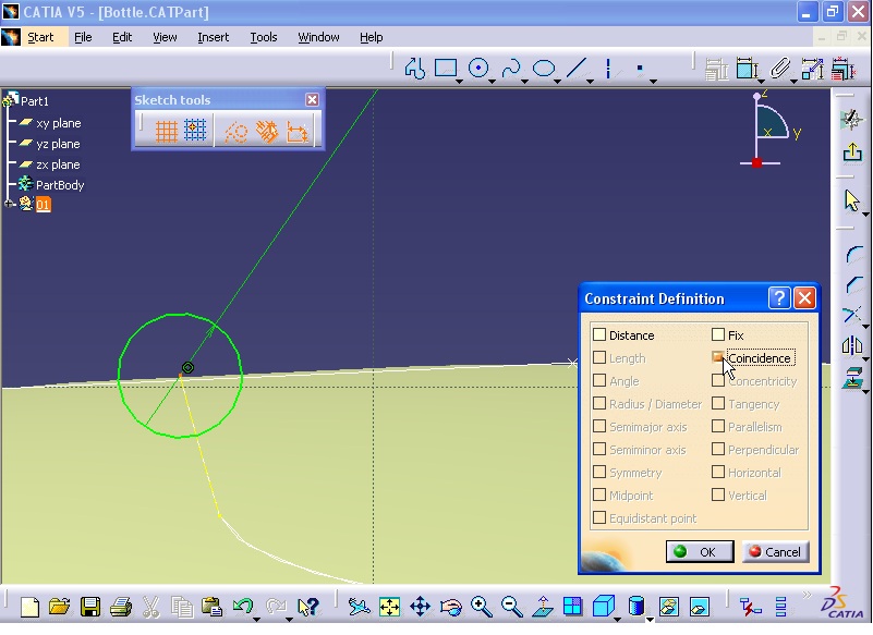
Now the ellipse will be connected to the start points of the splines. To do this, press Ctrl button and hold it, meanwhile select the start point of one of the splines and the ellipse.

Then click on 'Constraints Defined in Dialog Box' command. Constraint Definition box opens. Select Coincidence option and click on OK.

Repeat the above procedure for the second point and ellipse. To do this, press Ctrl button and hold it, meanwhile select the start point of the other spline and the ellipse.

Then click on 'Constraints Defined in Dialog Box' command. Constraint Definition box opens. Select Coincidence option and click on OK.

Now the sketch image looks like the following image.

Now exit the Sketcher. To exit the sketcher double click on one of the splines.

Next the top face of the bottle is created. First a plane is created. The top face of the bottle will be created on the plane. Click on Plane command. Plane Definition window opens. In Plane type list select 'Parallel through point' option. For Reference section click on zx plane from tree.

For Point section, select either end points of the splines (Both end points have the same height - Z axis). Click on OK to close the Plane Definition window.

Now click on Sketch command and select the new plane.

Now you are in sketch workbench.


Now click on Circle command and select the origin as the center of the circle. Then click somewhere close to the end points of splines.

Now the circle will be connected to the end points of the splines. To do this, press Ctrl button and hold it, meanwhile select the start point of one of the splines and the circle.


Then click on 'Constraints Defined in Dialog Box' command. Constraint Definition box opens. Select Coincidence option and click on OK.

Repeat the above procedure for the second point and circle. To do this, press Ctrl button and hold it, meanwhile select the start point of the other spline and the circle.

Then click on 'Constraints Defined in Dialog Box' command. Constraint Definition box opens. Select Coincidence option and click on OK.

Finally exit the sketch.

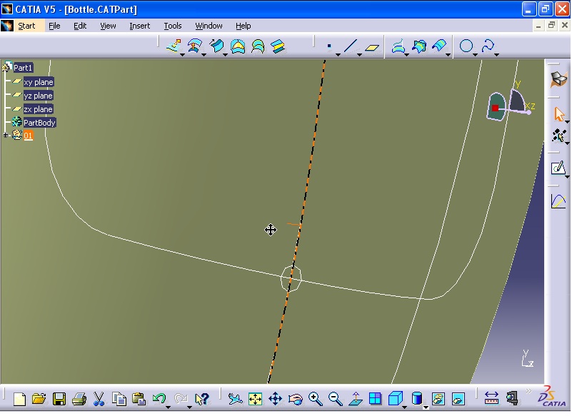
Next from Operations toolbar click on Symmetry command. Symmetry Definition window opens. For Element section, select Spline.1 as shown in the figure.

For Reference section, right click and select YZ Plane option.

Now click on OK.

Again from Operations toolbar click on Symmetry command. Symmetry Definition window opens. For Element section, select Spline.2 as shown in the figure.

For Reference section, right click and select XY Plane.

Then click on OK.

In next step the side surfaces of the bottle are created. From Surfaces toolbar, click on Multi-Sections Surface command. Multi-Sections Surface Definition window opens. For Section box first select the ellipse.

Then select the top circle.

For Guide section from Guide tab, select all the splines produced previously.

Now click on Preview.

Now from View toolbar select 'Shading with Edges' option. This will display the edges of the model.


As you see there is a extra edge on the surface model.

This edge connects two points of Closing point 1 and Closing point 2.


Right click on Closing point 2 and select Replace.

Then select the start point of the spline.


Repeat the procedure for Closing point 1. Right click on the Closing point 1 and select Replace option.

Then select the end point of the spline.


Now click on Preview. The extra edge is disappeared.

Click on OK.

Next, the top section of the bottle will be created. From Surfaces toolbar, click on Extrude command. Extruded Surface Definition window opens. For Profile section, select the circle.

In Dimension section enter 15 mm.

Then click on OK.

Next the bottom surface will be created. Click on Fill command from Surfaces toolbar. Fill Surface Definition window opens. For Curves section, select the ellipse sketch.

Then click on Preview and finally click on OK.


Next click on xy plane from tree.

Then click on Plane command to create a new plane. Plane Definition window opens. In Offset box enter 50 mm.

Click on OK.

As the new plane is selected, click on Sketch command.

Then from Profile toolbar, click on Axis command. Then for start point, click on the origin of the coordinate system.

For the second point, click somewhere in the vertical direction as shown in the figure.


Next double click on Line command. For the start point click somewhere on the new axis.

Then for the end point, click somewhere horizontally as shown in the figure.

Draw the second line perpendicular to the first line.

Draw the third line as shown in the figure.

Exit the Line command and click on Corner command from Operation toolbar. Click on the vertex and enter 12 mm for radius.

Repeat corner for the above vertex but enter 20 mm for the radius.

Then click on Constraint command, and constraint the sketch as shown in the figure.

Next press the Ctrl button and hold it and select all the sketch.

Then click on Mirror command. Then click on the vertical axis.

Now the sketch is complete.

Finally click on Corner command and select the top vertex and enter 24 mm for radius.

Constraint the inclined line (Length = 24 mm) as shown in the figure.

Now exit the sketcher.

Now the sketch will be projected on the surface. From Wireframe click on Projection command. Projection Definition window opens. For Projected section click on the sketch which was created in previous section. For Support section click on the surface model.

Then click on Preview.

Then click on OK.

Hide the sketch by right click on the sketch and hide it.

Next click on yz plane

And click on Sketch command.

Then click on Circle command and create a circle anywhere you want. The diameter of the circle is 2.5 mm.

Then click on Project 3D Elements command. Then select the curve as shown in the figure.

As the curve is selected click on Construction command.

Then press Ctrl button and hold it then select the center of the circle and the start point of the projected curve which is a point.


Next create a coincidence constraint between the center of the circle and the projected curve (point). To do this, click on 'Constraints Defined in Dialog Box' button. Constraint Definition window opens. Select Coincidence option and click OK.

Then exit the sketch.

Next, click on Sweep. Swept Surface Definition window opens. For Profile type select Explicit option and in Subtype section select 'With reference surface' option. For Profile section, select the circle.

For 'Guide curve' section, select the projected curve.

Then click on Preview.

Then click on OK.

Now the intersection between the swept surface and the body surface will be filleted. To do this you need to go to Generative Shape Design workbench. From menu click on Start - Shape - Generative Shape Design.

Then from menu click on Insert - Operations - Shape Fillet.

Fillet Definition window opens. For Support 1 section click on the main surface body.

For Support 2 section click on the swept surface.
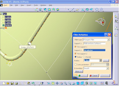
For Radius section, enter 0.5 mm. Make sure that the direction of the arrows appeared on the selected surfaces should be outward.


Now click on OK.

Next, the top section of the model will be filleted. Again from menu click on Insert - Operations - Shape Fillet.

Fillet Definition window opens. For Support 1 section click on the extruded surface.

For Support 2 section, click on the body surface.

For Radius section enter 1.5 mm.

Then click on OK.


In next step, the bottom section of the model will be filleted through Variable Radius Fillet command. First hide the ellipse sketch. Right click on the ellipse and select Hide/Show option.

Note that at the moment this edge is the intersection of two separate surfaces (Fill.1 and Fillet.2) and it is impossible to use the fillet command.

To solve the problem, click on Join command from Operations toolbar or click on Insert - Operations- Join.

Join Definition window opens. For 'Elements To Join' section select the two intersecting surfaces.

Click on OK. The surfaces now joined together. Join.1 is added to the tree.

On the other hand, to use variable fillet command we need to create some points on the edge. Therefore, to create the symmetry of the point, from menu click on Insert - Operations - Symmetry.

Symmetry Definition window opens. Click on the point as shown in the figure.
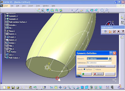
In Reference section, right click and select XY Plane.

Now the point resulted from symmetry command is created. Then click on OK.

To create the other point at the other side, from menu click on Insert - Operations - Symmetry.

Symmetry Definition window opens. Click on the point as shown in the figure.

In Reference section, right click and select YZ Plane.

Click on OK. the point resulted from symmetry command is created.

Next from menu click on Insert - Operations - Variable Fillet.

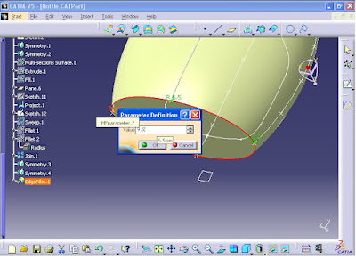
Variable Radius Fillet Definition window opens. For Edge(s) to fillet section, click on the bottom edge of the model as shown in the figure.

As you in Points section 2 points are considered for variable fillet. Now click on Points section. Then click on the other points which were created through symmetry command.


Now at each point, a radius value is appeared. By double-clicking on each radius you can modify the radius. Now for two points located on the small radius of the ellipse, enter 6.5 mm for the radius of the fillet.

Repeat the above procedure for the other point and enter 6.5 mm for the radius and click on OK.

For the other two points located on the large radius of the ellipse, double click on the radius and enter 9.5 mm and click on OK.
For the last point, repeat the above procedure and enter 9.5 mm and click on OK.

From 'Variation' list select Linear option.

Click on OK.

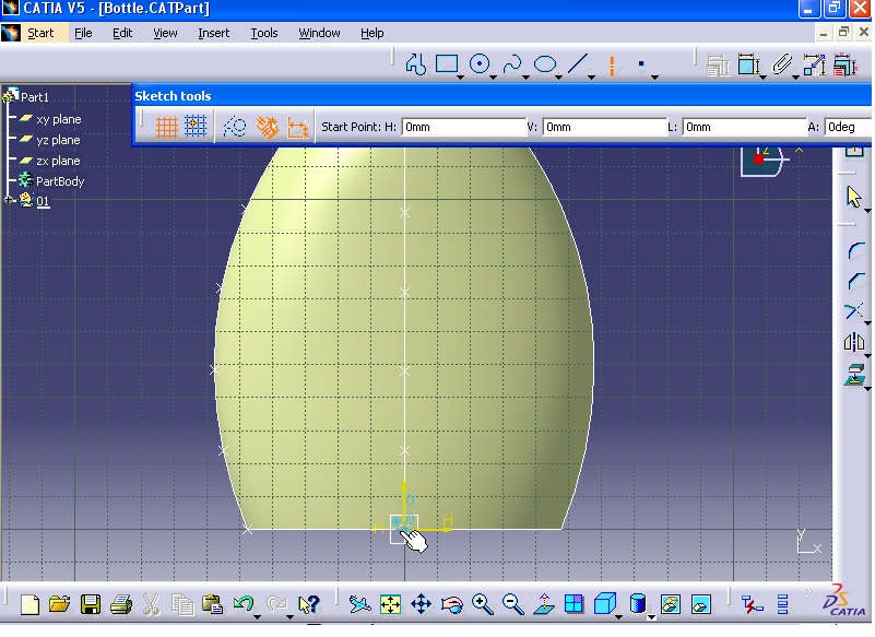
Now hide all the sketches, points, curves, and planes by selecting them from tree. Then right click on them and hide them

Now the model looks like the following image.

In next stage, the threads at top section will be created. First click on Plane command. Plane Definition window opens. From Plane type list select 'Offset from plane' option. For Reference section, right click on it and select ZX Plane.

In Offset section, enter 244 mm and click on Preview.

Then click on OK. Then click on Point command and from Point type list select 'On curve' option. For Curve click on somewhere at top edge of the model as shown in the figure.

Then in Ratio section, enter 0 and click OK.


Now the point will be projected on the new plane. From Wireframe toolbar, click on Projection command. Projection Definition window opens. For Projected section click on the point.

For Support section, click on the plane.

Then click on OK.

Next, the central axis will be created. Therefore from Wireframe toolbar click on Axis command. Axis Definition window opens. For Element section click on the top edge of the model.

From Axis type list select 'Normal to circle' option.

Click on OK.

From Wireframe toolbar click on Helix command. Helix Curve Definition window opens. For Starting Point, click on the projected point.

For Axis section, click on the new axis.

In Pitch section, enter 5 mm. In Height section, enter 7 mm. Click on Reverse Direction, to change the direction of the helix downwards.

Then click on OK.

The profile of the thread is already created in a separated file and is similar to the following image.

Next, the plane which contains the sketch will be created. Click on Plane command. From Plane type list select Normal to curve option. For Curve section click on the Helix.

In Point section, click on the projected point.

Then click on OK.

Then click on Sketch command and select the new plane.

Now bring the thread file which has the profile thread and select all the thread sketch. Then from menu click on Edit - Copy.

Next switch to the main model file.

From menu click on Edit - Paste.


Press Ctrl button and hold it then select the corner of the profile as shown in the figure.

As you press the Ctrl, select another point.

Then click on 'Constraints Defined in Dialog Box' command. Constraint Definition window opens. Select Coincidence option.

Then click on OK.

Constraint the horizontal line of the profile and the surface with parallelism. Select the both line and the surface.


Then click on 'Constraints Defined in Dialog Box' command. Constraint Definition window opens. Select Parallelism option.

Click on OK. The Parallelism constraint is created between the axis and the horizontal line of the profile.

Then exit the Sketcher. Next from Surfaces toolbar, click on Sweep command. Swept Surface Definition window opens. In Profile type select Explicit option. From Subtype list select 'With reference surface' option. For Profile section, click on the profile.

For Guide curve section, click on the Helix.

Then click on Preview.

Click on OK.

To finish the model, enter to the Part Design workbench. From menu click Start - Mechanical Design - Part Design.

From tree right click on PartBody and select 'Define In Work Object' option.

Next from menu click on Insert - Surface-Based Features - Close Surface.

Close Surface Definition window opens. For 'Object to close' section click on the thread.

Then click OK.

Next the surface body will be thickened. From menu click Insert - Surface-Based Features - Thick Surface.

Thick Surface Definition window opens. Then select the surface model.

For First Offset section, enter 1.5 mm and for Second Offset section enter 0.25 mm. Make sure that the direction of the arrows are towards inside. If not, click on Reverse Direction button.

Click on OK. The model is now complete.


For Reference section, right click and select YZ Plane option.

Now click on OK.

Again from Operations toolbar click on Symmetry command. Symmetry Definition window opens. For Element section, select Spline.2 as shown in the figure.

For Reference section, right click and select XY Plane.

Then click on OK.

In next step the side surfaces of the bottle are created. From Surfaces toolbar, click on Multi-Sections Surface command. Multi-Sections Surface Definition window opens. For Section box first select the ellipse.

Then select the top circle.

For Guide section from Guide tab, select all the splines produced previously.

Now click on Preview.

Now from View toolbar select 'Shading with Edges' option. This will display the edges of the model.


As you see there is a extra edge on the surface model.

This edge connects two points of Closing point 1 and Closing point 2.


Right click on Closing point 2 and select Replace.

Then select the start point of the spline.


Repeat the procedure for Closing point 1. Right click on the Closing point 1 and select Replace option.

Then select the end point of the spline.


Now click on Preview. The extra edge is disappeared.

Click on OK.

Next, the top section of the bottle will be created. From Surfaces toolbar, click on Extrude command. Extruded Surface Definition window opens. For Profile section, select the circle.

In Dimension section enter 15 mm.

Then click on OK.

Next the bottom surface will be created. Click on Fill command from Surfaces toolbar. Fill Surface Definition window opens. For Curves section, select the ellipse sketch.

Then click on Preview and finally click on OK.


Next click on xy plane from tree.

Then click on Plane command to create a new plane. Plane Definition window opens. In Offset box enter 50 mm.

Click on OK.

As the new plane is selected, click on Sketch command.

Then from Profile toolbar, click on Axis command. Then for start point, click on the origin of the coordinate system.
For the second point, click somewhere in the vertical direction as shown in the figure.


Next double click on Line command. For the start point click somewhere on the new axis.

Then for the end point, click somewhere horizontally as shown in the figure.

Draw the second line perpendicular to the first line.

Draw the third line as shown in the figure.

Exit the Line command and click on Corner command from Operation toolbar. Click on the vertex and enter 12 mm for radius.

Repeat corner for the above vertex but enter 20 mm for the radius.

Then click on Constraint command, and constraint the sketch as shown in the figure.

Next press the Ctrl button and hold it and select all the sketch.

Then click on Mirror command. Then click on the vertical axis.

Now the sketch is complete.

Finally click on Corner command and select the top vertex and enter 24 mm for radius.

Constraint the inclined line (Length = 24 mm) as shown in the figure.

Now exit the sketcher.

Now the sketch will be projected on the surface. From Wireframe click on Projection command. Projection Definition window opens. For Projected section click on the sketch which was created in previous section. For Support section click on the surface model.

Then click on Preview.

Then click on OK.

Hide the sketch by right click on the sketch and hide it.

Next click on yz plane

And click on Sketch command.

Then click on Circle command and create a circle anywhere you want. The diameter of the circle is 2.5 mm.

Then click on Project 3D Elements command. Then select the curve as shown in the figure.

As the curve is selected click on Construction command.

Then press Ctrl button and hold it then select the center of the circle and the start point of the projected curve which is a point.


Next create a coincidence constraint between the center of the circle and the projected curve (point). To do this, click on 'Constraints Defined in Dialog Box' button. Constraint Definition window opens. Select Coincidence option and click OK.
Then exit the sketch.
Next, click on Sweep. Swept Surface Definition window opens. For Profile type select Explicit option and in Subtype section select 'With reference surface' option. For Profile section, select the circle.

For 'Guide curve' section, select the projected curve.

Then click on Preview.

Then click on OK.

Now the intersection between the swept surface and the body surface will be filleted. To do this you need to go to Generative Shape Design workbench. From menu click on Start - Shape - Generative Shape Design.

Then from menu click on Insert - Operations - Shape Fillet.

Fillet Definition window opens. For Support 1 section click on the main surface body.

For Support 2 section click on the swept surface.

For Radius section, enter 0.5 mm. Make sure that the direction of the arrows appeared on the selected surfaces should be outward.


Now click on OK.

Next, the top section of the model will be filleted. Again from menu click on Insert - Operations - Shape Fillet.

Fillet Definition window opens. For Support 1 section click on the extruded surface.

For Support 2 section, click on the body surface.

For Radius section enter 1.5 mm.

Then click on OK.


In next step, the bottom section of the model will be filleted through Variable Radius Fillet command. First hide the ellipse sketch. Right click on the ellipse and select Hide/Show option.

Note that at the moment this edge is the intersection of two separate surfaces (Fill.1 and Fillet.2) and it is impossible to use the fillet command.

To solve the problem, click on Join command from Operations toolbar or click on Insert - Operations- Join.

Join Definition window opens. For 'Elements To Join' section select the two intersecting surfaces.

Click on OK. The surfaces now joined together. Join.1 is added to the tree.

On the other hand, to use variable fillet command we need to create some points on the edge. Therefore, to create the symmetry of the point, from menu click on Insert - Operations - Symmetry.

Symmetry Definition window opens. Click on the point as shown in the figure.

In Reference section, right click and select XY Plane.

Now the point resulted from symmetry command is created. Then click on OK.

To create the other point at the other side, from menu click on Insert - Operations - Symmetry.

Symmetry Definition window opens. Click on the point as shown in the figure.

In Reference section, right click and select YZ Plane.

Click on OK. the point resulted from symmetry command is created.

Next from menu click on Insert - Operations - Variable Fillet.

Variable Radius Fillet Definition window opens. For Edge(s) to fillet section, click on the bottom edge of the model as shown in the figure.

As you in Points section 2 points are considered for variable fillet. Now click on Points section. Then click on the other points which were created through symmetry command.


Now at each point, a radius value is appeared. By double-clicking on each radius you can modify the radius. Now for two points located on the small radius of the ellipse, enter 6.5 mm for the radius of the fillet.

Repeat the above procedure for the other point and enter 6.5 mm for the radius and click on OK.

For the other two points located on the large radius of the ellipse, double click on the radius and enter 9.5 mm and click on OK.

For the last point, repeat the above procedure and enter 9.5 mm and click on OK.

From 'Variation' list select Linear option.

Click on OK.

Now hide all the sketches, points, curves, and planes by selecting them from tree. Then right click on them and hide them

Now the model looks like the following image.

In next stage, the threads at top section will be created. First click on Plane command. Plane Definition window opens. From Plane type list select 'Offset from plane' option. For Reference section, right click on it and select ZX Plane.

In Offset section, enter 244 mm and click on Preview.

Then click on OK. Then click on Point command and from Point type list select 'On curve' option. For Curve click on somewhere at top edge of the model as shown in the figure.

Then in Ratio section, enter 0 and click OK.


Now the point will be projected on the new plane. From Wireframe toolbar, click on Projection command. Projection Definition window opens. For Projected section click on the point.

For Support section, click on the plane.

Then click on OK.

Next, the central axis will be created. Therefore from Wireframe toolbar click on Axis command. Axis Definition window opens. For Element section click on the top edge of the model.

From Axis type list select 'Normal to circle' option.

Click on OK.

From Wireframe toolbar click on Helix command. Helix Curve Definition window opens. For Starting Point, click on the projected point.

For Axis section, click on the new axis.

In Pitch section, enter 5 mm. In Height section, enter 7 mm. Click on Reverse Direction, to change the direction of the helix downwards.

Then click on OK.

The profile of the thread is already created in a separated file and is similar to the following image.

Next, the plane which contains the sketch will be created. Click on Plane command. From Plane type list select Normal to curve option. For Curve section click on the Helix.

In Point section, click on the projected point.

Then click on OK.

Then click on Sketch command and select the new plane.

Now bring the thread file which has the profile thread and select all the thread sketch. Then from menu click on Edit - Copy.

Next switch to the main model file.

From menu click on Edit - Paste.


Press Ctrl button and hold it then select the corner of the profile as shown in the figure.

As you press the Ctrl, select another point.

Then click on 'Constraints Defined in Dialog Box' command. Constraint Definition window opens. Select Coincidence option.

Then click on OK.

Constraint the horizontal line of the profile and the surface with parallelism. Select the both line and the surface.


Then click on 'Constraints Defined in Dialog Box' command. Constraint Definition window opens. Select Parallelism option.

Click on OK. The Parallelism constraint is created between the axis and the horizontal line of the profile.

Then exit the Sketcher. Next from Surfaces toolbar, click on Sweep command. Swept Surface Definition window opens. In Profile type select Explicit option. From Subtype list select 'With reference surface' option. For Profile section, click on the profile.

For Guide curve section, click on the Helix.

Then click on Preview.

Click on OK.

To finish the model, enter to the Part Design workbench. From menu click Start - Mechanical Design - Part Design.

From tree right click on PartBody and select 'Define In Work Object' option.

Next from menu click on Insert - Surface-Based Features - Close Surface.

Close Surface Definition window opens. For 'Object to close' section click on the thread.

Then click OK.

Next the surface body will be thickened. From menu click Insert - Surface-Based Features - Thick Surface.

Thick Surface Definition window opens. Then select the surface model.

For First Offset section, enter 1.5 mm and for Second Offset section enter 0.25 mm. Make sure that the direction of the arrows are towards inside. If not, click on Reverse Direction button.

Click on OK. The model is now complete.


===========================================================