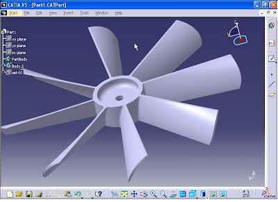
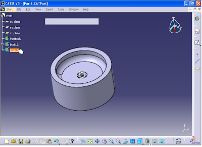
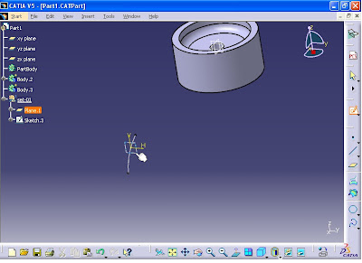
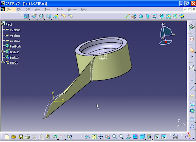
The exercise is about modeling a rotary fan as shown in the figure.
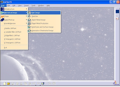
From menu click on Start - Mechanical Design - Part Design.
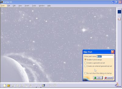
Then create a new part by clicking on OK.
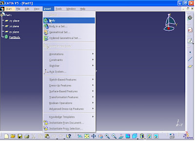
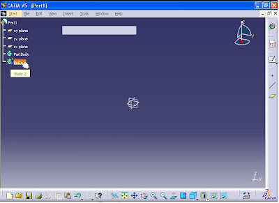
From menu click Insert - Body.
Body.2 is added to the tree.
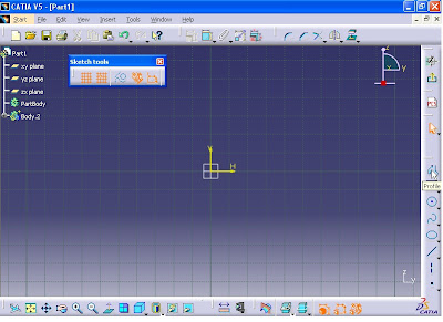
Then click on Sketch icon and select yz plane.

Then click on Profile command.
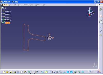
And create the sketch as shown in the figure.

Exit the Sketch workbench.
Then from menu click on Insert - Sketch-Based Features - Shaft.
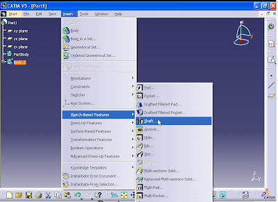
Shaft Definition window opens. Make sure that 'First angle' is 360 degree and 'Second angle' is 0 degree. And also make sure that in Profile/Surface section Sketch.1 is selected. Otherwise select the sketch.
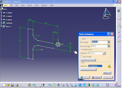
In Axis section right click and select Z Axis option.
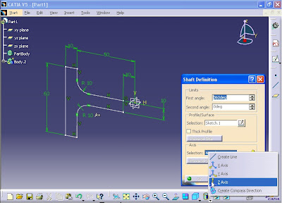
Then click on Preview button.

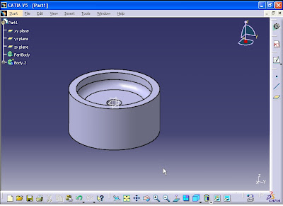
Then click on OK.
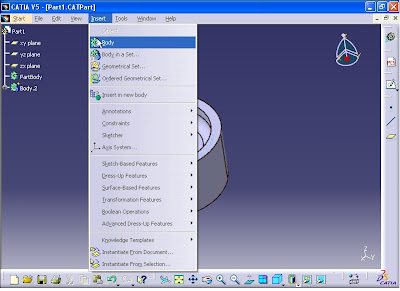
Next, from menu click on Insert - Body.
Body.3 is added to the tree.
Then from menu click on Insert - Geometrical Set.
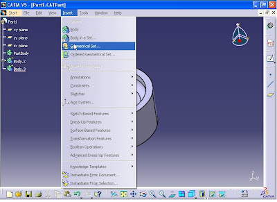
Insert Geometrical Set window opens. In Name box enter set-01 and click OK.

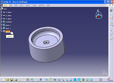
set-01 is added to the tree.
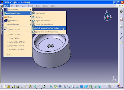
Then from menu click on Start - Mechanical Design - Wireframe and Surface Design.
Then click on Plane command. Plane Definition window opens.
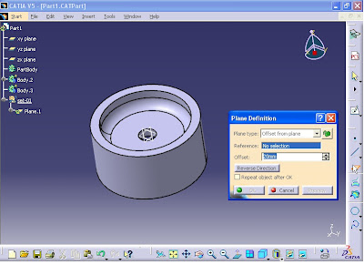
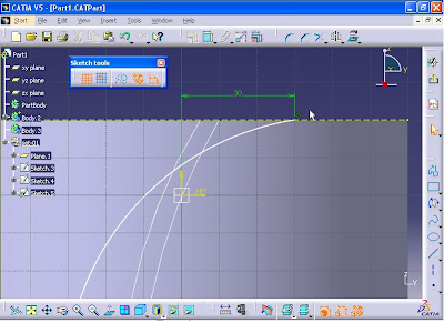
From Plane type select Offset from plane option. For Reference click on yz plane.
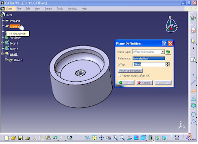
Then in Offset enter 300 mm and click on Preview.

Click OK.

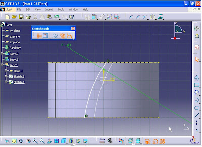
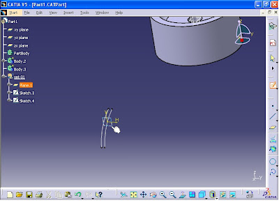
Next click on Sketch button and for sketch plane click on the new plane (Plane.1).

Then create the sketch as shown in the figure.
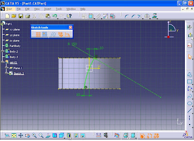
Then exit the Sketch workbench.
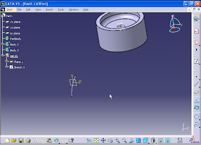
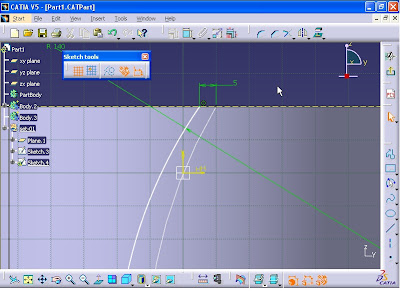
Again click on Sketch button and select the plane.1.
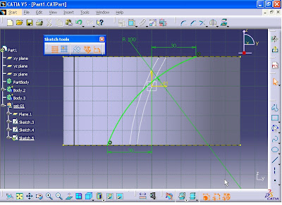
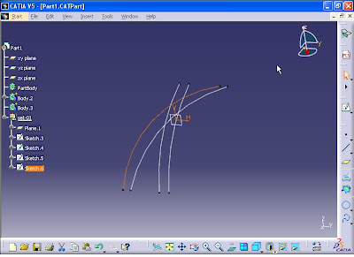
Then create a curve as shown in the figure.
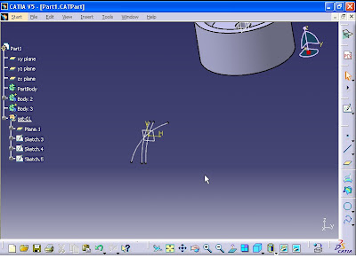
Then exit the Sketch workbench.

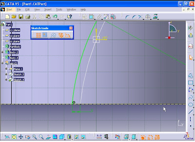
Again click on Sketch command and select Plane.1.
Create a curve as shown in the figure.
Then exit the Sketch workbench.
Again click on Sketch and select Plane.1.
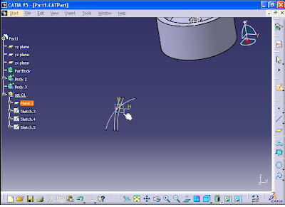
Create a curve as shown in the figure.

Then exit the Sketch workbench.
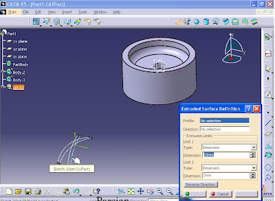
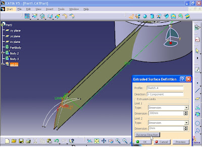
Then click on Extrude from Surfaces toolbar. Extruded Surface Definition window opens. For Profile section click on the first curve as shown in the figure.
In Direction section right click and select X Component.
Then in Limit 1 section for Dimension enter 300 mm. Then click on Reverse Direction button.
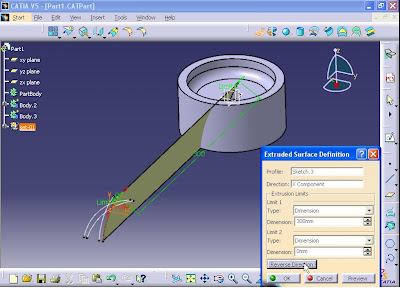
Then click on OK.
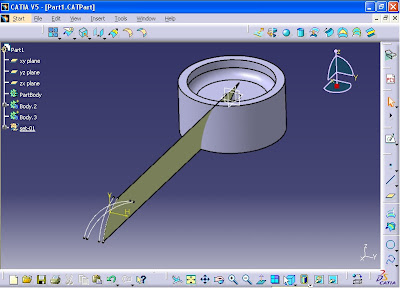
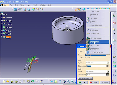
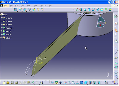
Again click on Extrude command. Extruded Surface Definition window opens. For Profile section click on the second curve as shown in the figure.
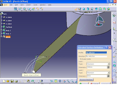
Then Right click in Direction section and select X Component.
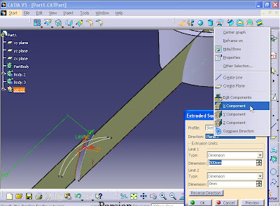
Then click on Reverse Direction button.
And click OK.
Then the external surface of the cylinder will be extracted.
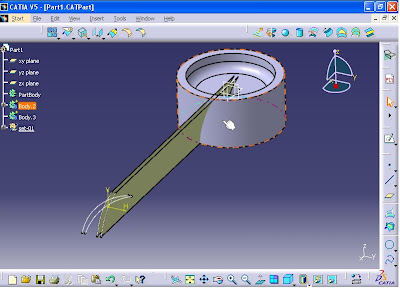
Therefore click on Extract from Operations toolbar. Extract Definition window opens. In Element(s) to extract section click on the outer surface of the cylinder.
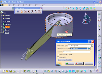
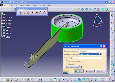
Then click on OK.
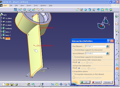
To create the common sections of the intersecting curves, click on Intersection command from Wireframe toolbar. Intersection Definition window opens. In First Element section click on Extract.1.
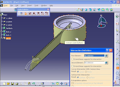
In Second Element section click on Extrude.1.

Then click on OK. The intersection curve is created as shown in the figure.
Again click on Intersection command from Wireframe toolbar. Intersection Definition window opens. In First Element and Second Element sections click on Extract.1 and Extrude.2 respectively.
Click on OK.
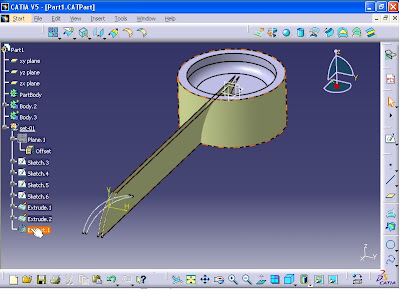
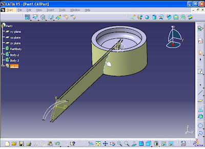
Hide Extrude.1 and Extrude.2 by right clicking on them and selecting Hide/Show option.
Hide Sketch.2 and Sketch.3 by right clicking on them and selecting Hide/Show option.
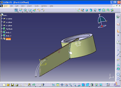
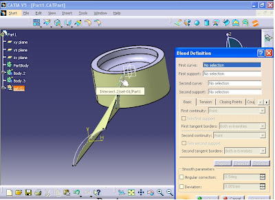
Now click on Blend command from Surfaces toolbar. Blend Definition window opens. In First curve section click on the Intersect.1 curve as shown in the figure.
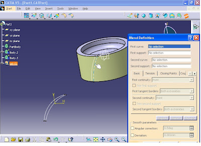
For Second curve click on the Sketch.5.

Make sure that the direction of the arrows are in the same direction.

Click on Preview.
Click on OK.
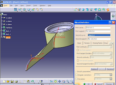
Again click on Blend command from Surfaces toolbar. Blend Definition window opens. In First curve section click on the Intersect.2 curve as shown in the figure.
For Second curve click on Sketch.6.

Make sure that the direction of the arrows are in the same direction.


From menu click on Start - Mechanical Design - Part Design.

Then create a new part by clicking on OK.

From menu click Insert - Body.

Body.2 is added to the tree.

Then click on Sketch icon and select yz plane.

Then click on Profile command.

And create the sketch as shown in the figure.

Exit the Sketch workbench.

Then from menu click on Insert - Sketch-Based Features - Shaft.

Shaft Definition window opens. Make sure that 'First angle' is 360 degree and 'Second angle' is 0 degree. And also make sure that in Profile/Surface section Sketch.1 is selected. Otherwise select the sketch.

In Axis section right click and select Z Axis option.

Then click on Preview button.

Then click on OK.

Next, from menu click on Insert - Body.

Body.3 is added to the tree.

Then from menu click on Insert - Geometrical Set.

Insert Geometrical Set window opens. In Name box enter set-01 and click OK.

set-01 is added to the tree.

Then from menu click on Start - Mechanical Design - Wireframe and Surface Design.

Then click on Plane command. Plane Definition window opens.

From Plane type select Offset from plane option. For Reference click on yz plane.

Then in Offset enter 300 mm and click on Preview.

Click OK.

Next click on Sketch button and for sketch plane click on the new plane (Plane.1).

Then create the sketch as shown in the figure.

Then exit the Sketch workbench.

Again click on Sketch button and select the plane.1.

Then create a curve as shown in the figure.


Then exit the Sketch workbench.

Again click on Sketch command and select Plane.1.

Create a curve as shown in the figure.


Then exit the Sketch workbench.

Again click on Sketch and select Plane.1.

Create a curve as shown in the figure.

Then exit the Sketch workbench.

Then click on Extrude from Surfaces toolbar. Extruded Surface Definition window opens. For Profile section click on the first curve as shown in the figure.

In Direction section right click and select X Component.

Then in Limit 1 section for Dimension enter 300 mm. Then click on Reverse Direction button.

Then click on OK.

Again click on Extrude command. Extruded Surface Definition window opens. For Profile section click on the second curve as shown in the figure.

Then Right click in Direction section and select X Component.

Then click on Reverse Direction button.

And click OK.

Then the external surface of the cylinder will be extracted.

Therefore click on Extract from Operations toolbar. Extract Definition window opens. In Element(s) to extract section click on the outer surface of the cylinder.


Then click on OK.

To create the common sections of the intersecting curves, click on Intersection command from Wireframe toolbar. Intersection Definition window opens. In First Element section click on Extract.1.

In Second Element section click on Extrude.1.

Then click on OK. The intersection curve is created as shown in the figure.

Again click on Intersection command from Wireframe toolbar. Intersection Definition window opens. In First Element and Second Element sections click on Extract.1 and Extrude.2 respectively.

Click on OK.

Hide Extrude.1 and Extrude.2 by right clicking on them and selecting Hide/Show option.


Hide Sketch.2 and Sketch.3 by right clicking on them and selecting Hide/Show option.


Now click on Blend command from Surfaces toolbar. Blend Definition window opens. In First curve section click on the Intersect.1 curve as shown in the figure.

For Second curve click on the Sketch.5.

Make sure that the direction of the arrows are in the same direction.

Click on Preview.

Click on OK.

Again click on Blend command from Surfaces toolbar. Blend Definition window opens. In First curve section click on the Intersect.2 curve as shown in the figure.

For Second curve click on Sketch.6.

Make sure that the direction of the arrows are in the same direction.

Then click on Preview.

Click on OK.

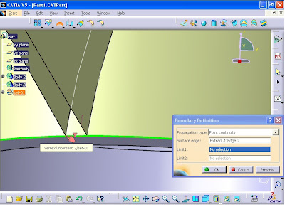
From Operations toolbar click on Boundary. Boundary Definition window opens. In Propagation type select 'Point continuity' option. For Surface edge section click on the edge as shown in the figure.
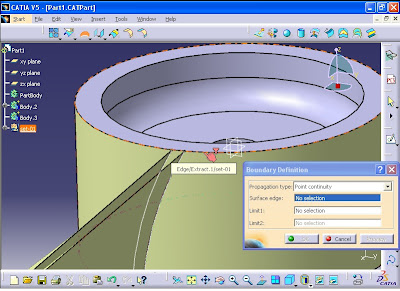
For Limit1 select the vertex as shown in the figure.
For Limit2 click on the vertex as shown in the figure.
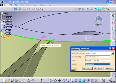
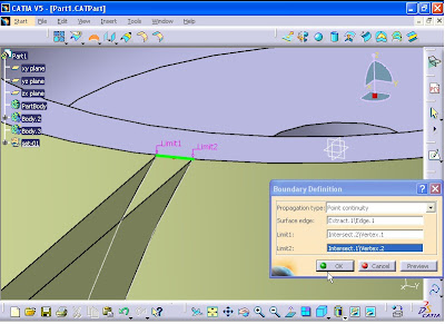
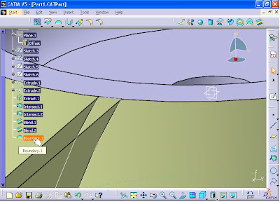
Click on OK. Boundary.1 is added to the tree.
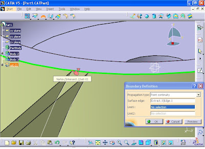
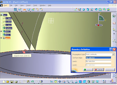
Again repeat the above procedure for the bottom section. From Operations toolbar click on Boundary. Boundary Definition window opens. In Propagation type select 'Point continuity' option. For Surface edge section click on the edge as shown in the figure.
For Limit1 select the vertex as shown in the figure.
Click on the arrow to change the direction towards right.
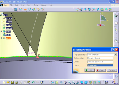
For Limit2 click on the vertex as shown in the figure.

Then click on OK.

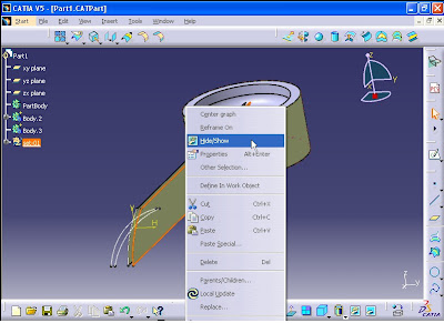
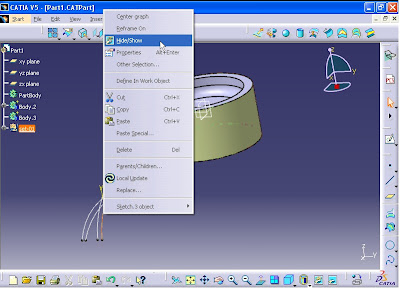
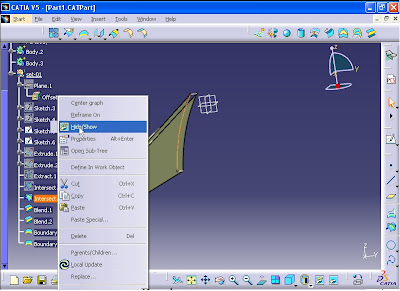
Hide the cylinder surface by right clicking on it and selecting Hide/Show option.
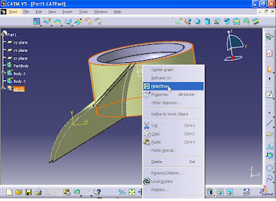
Hide the cylinder solid model as well.
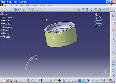
Hide the sketches of Intersect.1 and Intersect.2 as shown in the figure.
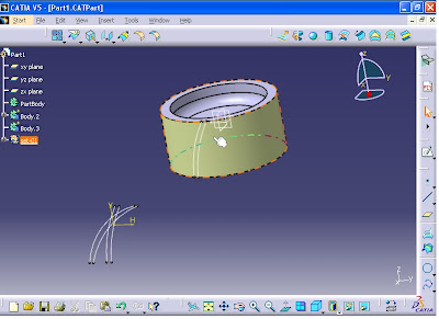
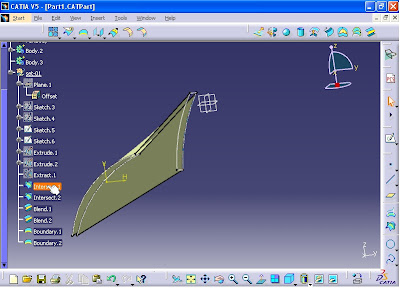
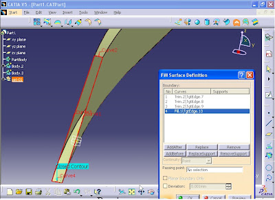
Now click on Fill command from Surfaces toolbar. Fill Surface Definition window opens. For Curves section, select the edges and curves as shown in the figure.
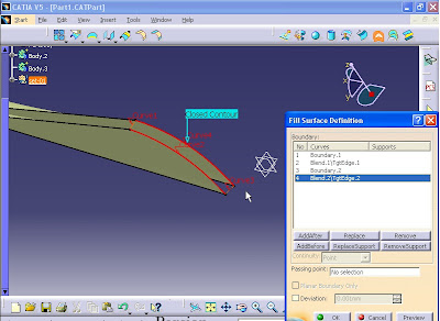
Then click on Preview.
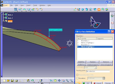
Click on OK.
In next stage click on Sketch button and select zx plane.

Then create a curve sketch as shown in the figure.

Then exit the Sketch workbench.
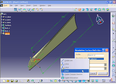
Then click on Revolve command from Surfaces toolbar. Revolution Surface Definition window opens. For Profile section click on the new sketch.
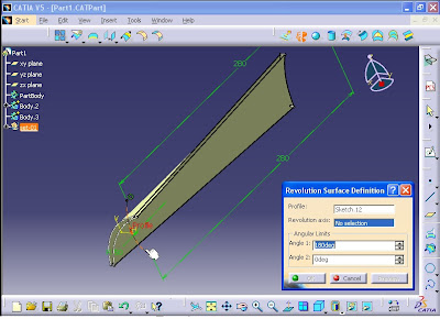
In Revolution Axis right click and Z Axis option.
In Angle 1 and Angle 2 boxes enter 14 and 16 degree respectively.
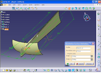
Click on OK.

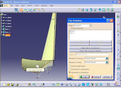
Then click on Trim from Operations toolbar. Trim Definition window opens. In Trimmed elements section, click on the right hand side surface of the blade as shown in the figure.
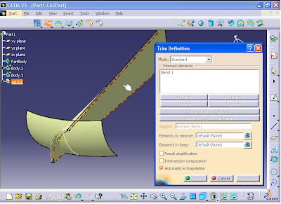
Then select the revolved surface.
Click on 'Other side/previous element' button to select the other side of the revolved surface.
And click on OK.
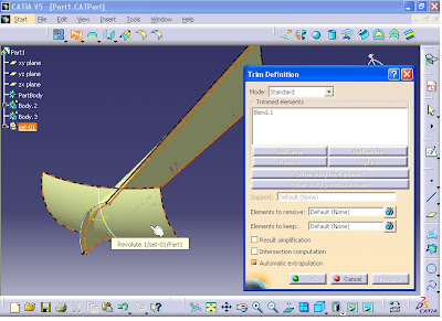
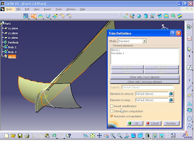
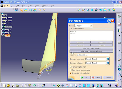
Again click on Trim command and repeat above procedure for the left side of the revolved surface. For Trimmed element section click on the right hand side surface of the blade as shown in the figure.

Then select the revolved surface.
Click on 'Other side/previous element' button to select the other side of the revolved surface then click on OK.
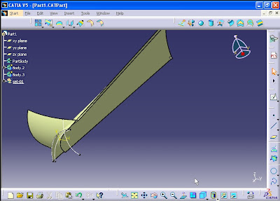
Now hide the sketches and curves.

Next click on Fill command from Surfaces toolbar. Fill Surface Definition window opens. For Curves section click on the top four edges of the surfaces respectively, as shown in the figure.
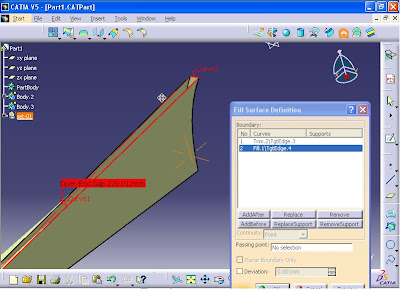
Then click on OK.
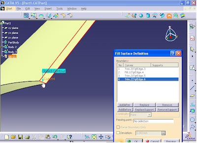
Again click on Fill command from Surfaces toolbar. Fill Surface Definition window opens. For Curves section click on the bottom four edges of the surfaces respectively, as shown in the figure.
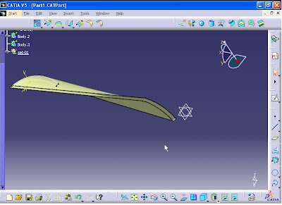
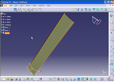
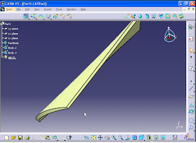
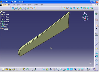
Click on OK. Now the rotary fan blade model is complete.
To join the surfaces, from Operations toolbar click on Join command. Join Definition window opens. In Elements To Join section select all the surfaces. Then click on OK.

To make sure that all the surfaces are selected, from tree right click on Join.1 and select Hide/Show option.
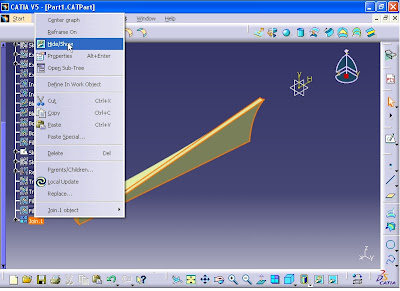
None of the surfaces would be shown.
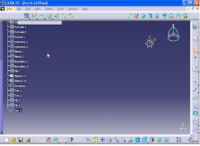
Again show the model.

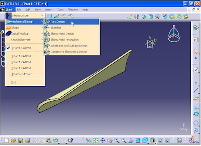
Now enter Part Design workbench. From menu click on Start - Mechanical Design - Part Design.
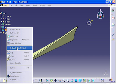
Then on Body.3 from tree right click and select 'Define In Work Object' option.
Now the surface model will be converted to a solid model. From menu click on Insert - Surface-Based Features - Close Surface.
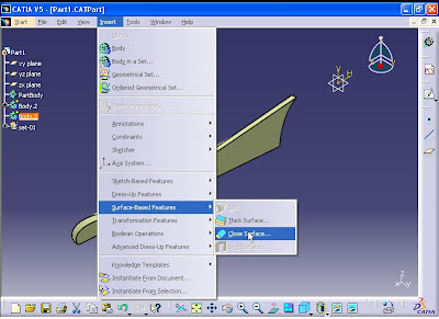
Close Surface Definition window opens. In Object to close section click on the surface model which is Join.1.
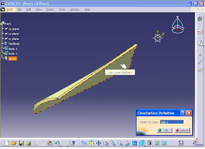
Then click on OK. Then right click on set-01 from tree and select Hide/Show option.
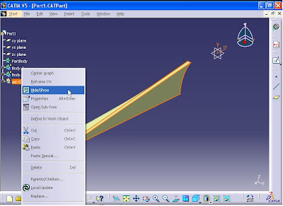
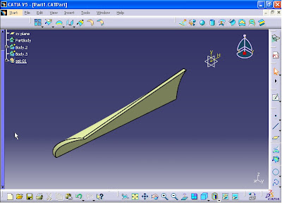
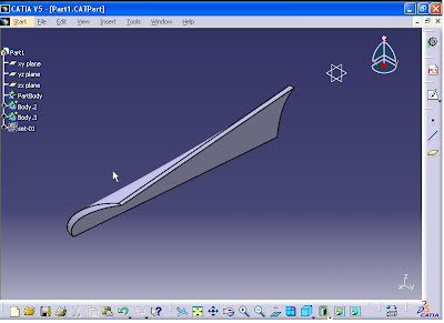
Now the solid model of the surface is created.
From tree right click on Shaft.1 and select Hide/Show option.
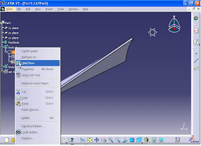
The central cylinder appears.
Now from menu click on View - Toolbars - Transformation Features.
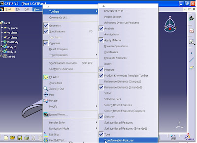
Transformation Features toolbar appears.
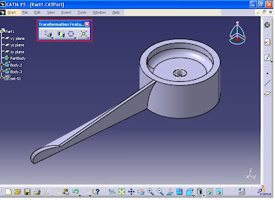
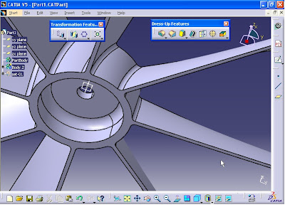
From Transformation Features, click on Circular Pattern command. Circular Pattern Definition window opens. On Reference element section right click and select Z Axis option.
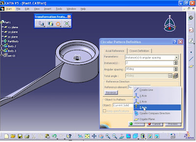
In Object to pattern section select the blade.
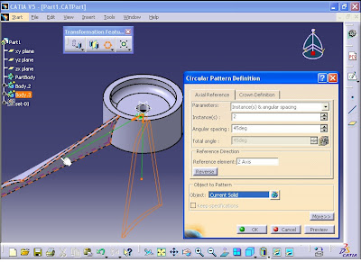
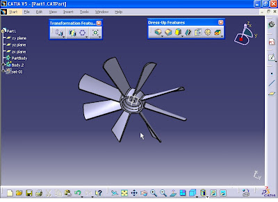
In Instance(s) section enter 8 and click on Preview.
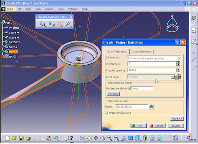
Then click on OK.

Next from menu click on View - Toolbars - Boolean Operations.

Boolean Operations toolbar opens.

Now from Boolean Operations toolbar click on Assemble. Assemble window opens. For Assemble section click on Body.3.
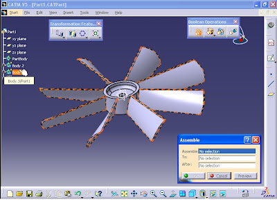
In 'To' section select Body.2 which is the cylinder part.
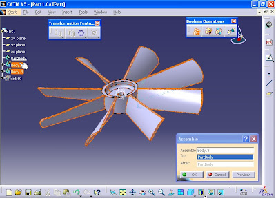
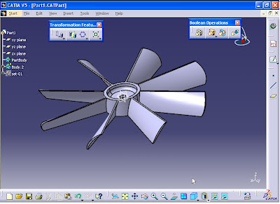
Then click on OK. The model is a unit solid model.
Again from menu click View - Toolbars - Dress-Up Features.

Dress-Up Features toolbar appears.

Click on Edge Fillet command from Dress-Up Features toolbar. Edge Fillet Definition window opens. In Object(s) to fillet section select all the edges which has been created through intersection of blades and the cylinder.
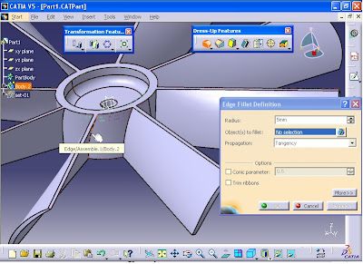
In Object(s) to fillet section, 16 elements must be appeared.
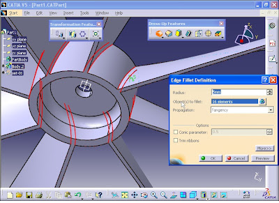
In Radius box enter 5 mm and in Propagation list select Tangency then click on OK.
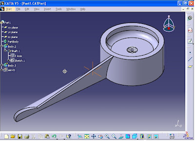
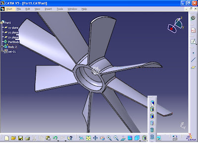
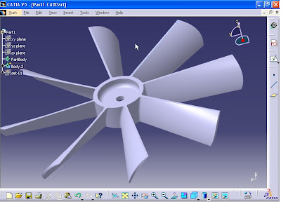
Now the model is completed.
Then click on Shading (SHD) command.

For Limit1 select the vertex as shown in the figure.

For Limit2 click on the vertex as shown in the figure.


Click on OK. Boundary.1 is added to the tree.

Again repeat the above procedure for the bottom section. From Operations toolbar click on Boundary. Boundary Definition window opens. In Propagation type select 'Point continuity' option. For Surface edge section click on the edge as shown in the figure.

For Limit1 select the vertex as shown in the figure.

Click on the arrow to change the direction towards right.

For Limit2 click on the vertex as shown in the figure.

Then click on OK.

Hide the cylinder surface by right clicking on it and selecting Hide/Show option.

Hide the cylinder solid model as well.

Hide the sketches of Intersect.1 and Intersect.2 as shown in the figure.

Now click on Fill command from Surfaces toolbar. Fill Surface Definition window opens. For Curves section, select the edges and curves as shown in the figure.

Then click on Preview.

Click on OK.

In next stage click on Sketch button and select zx plane.

Then create a curve sketch as shown in the figure.

Then exit the Sketch workbench.

Then click on Revolve command from Surfaces toolbar. Revolution Surface Definition window opens. For Profile section click on the new sketch.

In Revolution Axis right click and Z Axis option.

In Angle 1 and Angle 2 boxes enter 14 and 16 degree respectively.

Click on OK.

Then click on Trim from Operations toolbar. Trim Definition window opens. In Trimmed elements section, click on the right hand side surface of the blade as shown in the figure.

Then select the revolved surface.

Click on 'Other side/previous element' button to select the other side of the revolved surface.

And click on OK.

Again click on Trim command and repeat above procedure for the left side of the revolved surface. For Trimmed element section click on the right hand side surface of the blade as shown in the figure.

Then select the revolved surface.

Click on 'Other side/previous element' button to select the other side of the revolved surface then click on OK.

Now hide the sketches and curves.

Next click on Fill command from Surfaces toolbar. Fill Surface Definition window opens. For Curves section click on the top four edges of the surfaces respectively, as shown in the figure.


Then click on OK.

Again click on Fill command from Surfaces toolbar. Fill Surface Definition window opens. For Curves section click on the bottom four edges of the surfaces respectively, as shown in the figure.

Click on OK. Now the rotary fan blade model is complete.

To join the surfaces, from Operations toolbar click on Join command. Join Definition window opens. In Elements To Join section select all the surfaces. Then click on OK.

To make sure that all the surfaces are selected, from tree right click on Join.1 and select Hide/Show option.

None of the surfaces would be shown.

Again show the model.


Now enter Part Design workbench. From menu click on Start - Mechanical Design - Part Design.

Then on Body.3 from tree right click and select 'Define In Work Object' option.

Now the surface model will be converted to a solid model. From menu click on Insert - Surface-Based Features - Close Surface.

Close Surface Definition window opens. In Object to close section click on the surface model which is Join.1.

Then click on OK. Then right click on set-01 from tree and select Hide/Show option.

Now the solid model of the surface is created.

From tree right click on Shaft.1 and select Hide/Show option.

The central cylinder appears.

Now from menu click on View - Toolbars - Transformation Features.

Transformation Features toolbar appears.

From Transformation Features, click on Circular Pattern command. Circular Pattern Definition window opens. On Reference element section right click and select Z Axis option.

In Object to pattern section select the blade.

In Instance(s) section enter 8 and click on Preview.

Then click on OK.

Next from menu click on View - Toolbars - Boolean Operations.

Boolean Operations toolbar opens.

Now from Boolean Operations toolbar click on Assemble. Assemble window opens. For Assemble section click on Body.3.

In 'To' section select Body.2 which is the cylinder part.

Then click on OK. The model is a unit solid model.

Again from menu click View - Toolbars - Dress-Up Features.

Dress-Up Features toolbar appears.

Click on Edge Fillet command from Dress-Up Features toolbar. Edge Fillet Definition window opens. In Object(s) to fillet section select all the edges which has been created through intersection of blades and the cylinder.

In Object(s) to fillet section, 16 elements must be appeared.

In Radius box enter 5 mm and in Propagation list select Tangency then click on OK.

Now the model is completed.

Then click on Shading (SHD) command.

