Sweep:
From Surfaces toolbar click on Sweep. There are 4 methods of sweep.

In this section the first method which is Explicit is considered. First select xy plane from specification tree.

Then change the view in a way that it is normal to the xy plane. Click on Normal View button. Now the view is normal to xy plane.

Then double click on Point command from Wireframe toolbar. Point Definition window opens. Create point 1 (0,0,0) and click OK.

Then from Point type list select 'On plane' option. In Plane section select xy plane.

Click somewhere to create the second point.

Now create another 6 points in xy plane with different coordinates. Then click on Cancel to close the window.

Next from Wireframe toolbar click on Spline command. Spline Definition window opens. Create a spline which pass through the 3 points. Select the first three points and connect them respectively. Then click OK.

Again click on Spline command. Spline Definition window opens. This time click on the rest of the three points and connect them respectively and click OK.

Now two curves are created.

Now click on Sketch icon.

Then click on zx plane for sketch plane.

Now it is ready to sketch in zx plane.

Now a new curve will be created which starts from the coordinate system origin and passes through the start of the the previous curve. To do this first from Sketch tools toolbar click on Construction/Standard Element button.

Then click on Project 3D Element button.

Then click on the start of the curve. This point is projected onto the zx plane.

Then click on Spline command from Wireframe toolbar and select the origin of the coordinate system.

Then click on somewhere for the second point and finally click on the projected point as shown in the figure.

Now press Esc button to end the spline.

As the spline is active, click on Construction button to deactivate it and exit Sketcher workbench by clicking on Exit workbench button.

There is a problem. The problem is that the start points of the two curves don not overlap each other.

To solve the problem, first click on Plane command. Plane Definition window opens. From Plane type list select 'Angle/Normal to plane' option. Then right click on Rotation axis section and select Create Line option.

Line Definition window opens. To define the line first click on the coordinate system origin. Then select the start point of the curve as shown in the figure.

Then click OK.

Then in Plane Definition window and in Reference section right click and select xy plane option.

Then click on 'Normal to plane' button then click on OK. Now the new plane pass through the line and is normal to the xy plane.

Next the new plane will be transformed to the plane on which the curve lay. This will solve the problem. To do this select Sketch.1 from tree.

Then from menu click Edit and click 'Sketch.1 object' and select 'Change Sketch Support' option.

A warning window appears. Click on OK.

Sketch Positioning window opens. In Reference section select the plane (Plane.1) which was created previously. Then click on OK to close the window.

Now as you can see from figure the start points of the two curves overlap each other.

Next again click on 'Sketch' command. and select the new plane (Plane.1).

Now you are in Plane.1 to start sketching. Click on Profile.

Now create a profile as shown in the figure. Then exit the sketcher.

The sketch now looks like the image below.

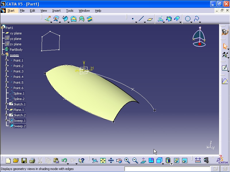
Next click on Sweep command from Surfaces button. Swept Surface Definition window opens. In Profile type there are 4 types of creating sweep. Select the first option which Explicit. In Subtype list select 'With reference surface' option. In Profile section click on Sketch.1.

In Guide curve select Spline.2.

In Surface section right click and select XY Plane.

Now click on Preview to see the result.

In Angle you can define the angle between the surface and the xy plane. For example enter 22 degree. Click Preview.

Then click OK.

Next select Sweep.1 from specification tree and right click on it and select Hide/Show option to hide the surface.
 ---------------------------------------------------
Sweep 1:
In this section the next option in Explicit is considered. From Surfaces toolbar click on Sweep. Swept Surface Definition window opens. Then from Subtype list select 'With two guide curves' option. In Profile section select Sketch.1. In Guide curve 1 and Guide curve 2 click on Spline.2 and Spline.1 respectively.

Click on Preview to see the result.

Click OK.

Now right click on Sweep.2 from tree and hide this surface.

Again click on Sweep from Surfaces toolbar. Swept Surface Definition window opens. Then from Subtype list select 'With two guide curves' option. In Profile section click on the profile.

Then in Guide curve 1 and 2 click on Spline.2 and Spline.1

Click on Preview.

Click on OK.

Then from tree right click on Sweep.3 and hide the surface.

The last option in Explicit mode is 'With pulling direction' option. Select the option from Subtype list. In Profile section select Sketch.1. In Guide curve section select Spline.1. For Direction section select xy plane from tree.

Click on Preview.

Click OK.

==========================================================
Second method of Sweep:
From Surfaces toolbar click on Sweep. Swept Surface Definition window opens. From Profile type click on the second button which is Line. From Subtype list select 'Two limits' option. For Guide curve one and two click on the first and second curve as shown in the figure.

Now click on Preview. As you see the left boundary of the surface is similar to left guide curve and the right boundary of the surface is similar to the right guide curve.

In Length 1 and Length 2 you can define the distance between the boundaries and the guide curves.

Click OK to end the command.

Now from menu click Edit and select 'Undo Sweep definition' command.


Again from Surfaces toolbar click on Sweep command. Swept Surface Definition window opens. Make sure that the Line icon from Profile type is selected. From Subtype list select 'Limit and middle' option. For Guide curve 1 select a straight line and for Guide curve 2 select a curve as shown in the figure.

Click on Preview. The surface is created in a way that the curve is located in the middle of the surface. Also the left hand boundary is similar to the middle curve.

Now click on Cancel button.

Again click on Sweep from Surfaces toolbar. Swept Surface Definition window opens. Make sure that the Line icon from Profile type is selected. From Subtype list select 'With reference surface' option. For 'Guide curve 1' select the curve. In Reference surface section right click and select XY Plane.

Click on Preview.

In Angle section you can define the angle between the Reference surface and the created surface.

In Length 1 and Length 2 you can define the distance between the boundaries and the curve guide.

Click Cancel.

Again click on Sweep from Surfaces toolbar. Swept Surface Definition window opens. Make sure that the Line icon from Profile type is selected. From Subtype list select 'With reference curve' option. For Guide curve 1 select the curve. For Reference curve select the straight line.

Click on Preview.

Enter 90 in Angle section. Then click Preview.

Now click on Cancel button.

Again click on Sweep from Surfaces toolbar. Swept Surface Definition window opens. Make sure that the Line icon from Profile type is selected. From Subtype list select 'With tangency surface' option. For Guide curve 1 select the curve. For Tangency surface section click on the surface.

Click on Preview.

Click on Cancel.

From Surfaces toolbar click on Sweep command. Swept Surface Definition window opens. Make sure that the Line icon from Profile type is selected. From Subtype list select 'With two tangency surfaces' option. In Spine section you need to select a direction of the surface. Right click on the Spine section and select X Axis option.

For 'First tangency surface' and 'Second tangency surface' section click on the two surfaces as shown in the figure.

Click on Preview.

Now click on OK.

==========================================================
Sweep (Circle):
From Surfaces toolbar click on Sweep command. Swept Surface Definition window opens. In Profile type click on third icon which is Circle icon. From Subtype list select 'Three guides' option. For Guide curve 1 to 3 select the curves respectively as shown in the figure.

Click on Preview.

Click on Cancel.

From Surfaces toolbar click on Sweep command. Swept Surface Definition window opens. In Profile type click on third icon which is Circle icon. From Subtype list select 'Two guides and radius' option. For Guide curve 1 and Guide curve 2 select the two curves. In Radius section you can define the curvature radius of the surface.

Click on Preview.


You can select the different curves by clicking on Next or Previous buttons.

Click on OK.

Next right click on the surface and select the Hide/show option.


From Surfaces toolbar click on Sweep command. Swept Surface Definition window opens. In Profile type click on third icon which is Circle icon. From Subtype list select 'Center and two angles' option. For Center curve select the curve as shown in the figure. For Reference curve select the straight line. In Angle 1 and 2 you can define the angles of the surface in two direction.

Click on Preview.


Click on Cancel.

Again from Surfaces toolbar click on Sweep command. Swept Surface Definition window opens. In Profile type click on third icon which is Circle icon. From Subtype list select 'Center and radius' option. For Center curve select the curve as shown in the figure. In Radius section which is the radius of the curvature of the surface, enter 38 mm. Then click on Preview.

Click on Cancel.

Again from Surfaces toolbar click on Sweep command. Swept Surface Definition window opens. In Profile type click on third icon which is Circle icon. From Subtype list select 'Two guides and tangency surface' option. For 'Limit curve with tangency' section select the curve. For Tangency surface section select the surface.

For Limit curve section click on the curve as shown in the figure.

Now click on Preview.

By clicking on the Next and Previous button you can select the surfaces resulted from the method. Now click on OK.

By rotating the model you can see the tangency between the surfaces.

Now hide this surface.

Again from Surfaces toolbar click on Sweep command. Swept Surface Definition window opens. In Profile type click on third icon which is Circle icon. From Subtype list select 'One guide and tangency surface' option. For Guide curve 1 select the curve as shown in the figure. For Tangency surface section select the surface. In Radius section select define the curvature radius of the surface.

Click on Preview.

Click OK.

Hide this new surface.

Again from Surfaces toolbar click on Sweep command. Swept Surface Definition window opens. In Profile type click on third icon which is Circle icon. From Subtype list select 'Limit curve and tangency surface' option. For Limit curve select the circle and for Tangency surface section click on the surface. For Radius, Angle 1 and Angle 2 define the curvature radius of the surface and angles of the surface at two sides.

Click on Preview.

Click OK.

==========================================================
Sweep (Conic):
From Surfaces toolbar click on Sweep command. Swept Surface Definition window opens. In Profile type click on fourth icon which is Conic icon. From Subtype list select 'Two guide curves' option. For Guide curve 1 select the curve. For Tangency section click on the surface close to the first guide curve.

For Last guide curve section click on the curve as shown in the figure. And for Tangency section click on the surface close to the last guide curve.

Click on Preview.

In Parameter section enter a value between 0 and 1. This parameter define the flatness and rate of inclined of the surface. For example enter 0.1 in the Parameter section. Click Preview.

Now enter 0.9 in the Parameter section and click Preview.

Enter 0.5 in Parameter section and click Preview.

In both Angle sections you can define the angle between the surface and the guide curves. Enter 45 in First Angle section and click Preview.

Then enter 30 in second Angle section and click Preview.

Now click on Cancel.

From Surfaces toolbar click on Sweep command. Swept Surface Definition window opens. In Profile type click on fourth icon which is Conic icon. From Subtype list select 'Three guide curves' option. For Guide curve 1 and Tangency section click on the curve and the surface close to the guide curve.

For Guide curve 2 select the middle curve as shown in the figure.

For Last guide curve and its Tangency section, click on the curve and the surface close to the guide curve as shown in the figure.

Then click on Preview.

Click on Cancel.

From Surfaces toolbar click on Sweep command. Swept Surface Definition window opens. In Profile type click on fourth icon which is Conic icon. From Subtype list select 'Four guide curves' option. For Guide curve 1 click on the curve. For Tangency section select the surface close to the guide curve 1 as shown in the figure.

For Guide curve 2 to 4 select the curves respectively as shown in the figure.

Click on Preview.

Click on Cancel.

From Surfaces toolbar click on Sweep command. Swept Surface Definition window opens. In Profile type click on fourth icon which is Conic icon. From Subtype list select 'Five guide curves' option. For Guide curve 1 to 5 select the curves respectively as shown in the figure.

Click on Preview.

Click OK.


Now create another 6 points in xy plane with different coordinates. Then click on Cancel to close the window.

Next from Wireframe toolbar click on Spline command. Spline Definition window opens. Create a spline which pass through the 3 points. Select the first three points and connect them respectively. Then click OK.

Again click on Spline command. Spline Definition window opens. This time click on the rest of the three points and connect them respectively and click OK.

Now two curves are created.

Now click on Sketch icon.

Then click on zx plane for sketch plane.

Now it is ready to sketch in zx plane.

Now a new curve will be created which starts from the coordinate system origin and passes through the start of the the previous curve. To do this first from Sketch tools toolbar click on Construction/Standard Element button.

Then click on Project 3D Element button.

Then click on the start of the curve. This point is projected onto the zx plane.

Then click on Spline command from Wireframe toolbar and select the origin of the coordinate system.

Then click on somewhere for the second point and finally click on the projected point as shown in the figure.

Now press Esc button to end the spline.

As the spline is active, click on Construction button to deactivate it and exit Sketcher workbench by clicking on Exit workbench button.

There is a problem. The problem is that the start points of the two curves don not overlap each other.

To solve the problem, first click on Plane command. Plane Definition window opens. From Plane type list select 'Angle/Normal to plane' option. Then right click on Rotation axis section and select Create Line option.

Line Definition window opens. To define the line first click on the coordinate system origin. Then select the start point of the curve as shown in the figure.

Then click OK.

Then in Plane Definition window and in Reference section right click and select xy plane option.

Then click on 'Normal to plane' button then click on OK. Now the new plane pass through the line and is normal to the xy plane.

Next the new plane will be transformed to the plane on which the curve lay. This will solve the problem. To do this select Sketch.1 from tree.

Then from menu click Edit and click 'Sketch.1 object' and select 'Change Sketch Support' option.

A warning window appears. Click on OK.

Sketch Positioning window opens. In Reference section select the plane (Plane.1) which was created previously. Then click on OK to close the window.

Now as you can see from figure the start points of the two curves overlap each other.

Next again click on 'Sketch' command. and select the new plane (Plane.1).

Now you are in Plane.1 to start sketching. Click on Profile.

Now create a profile as shown in the figure. Then exit the sketcher.

The sketch now looks like the image below.

Next click on Sweep command from Surfaces button. Swept Surface Definition window opens. In Profile type there are 4 types of creating sweep. Select the first option which Explicit. In Subtype list select 'With reference surface' option. In Profile section click on Sketch.1.

In Guide curve select Spline.2.

In Surface section right click and select XY Plane.

Now click on Preview to see the result.

In Angle you can define the angle between the surface and the xy plane. For example enter 22 degree. Click Preview.

Then click OK.

Next select Sweep.1 from specification tree and right click on it and select Hide/Show option to hide the surface.

Sweep 1:
In this section the next option in Explicit is considered. From Surfaces toolbar click on Sweep. Swept Surface Definition window opens. Then from Subtype list select 'With two guide curves' option. In Profile section select Sketch.1. In Guide curve 1 and Guide curve 2 click on Spline.2 and Spline.1 respectively.

Click on Preview to see the result.

Click OK.
Now right click on Sweep.2 from tree and hide this surface.

Again click on Sweep from Surfaces toolbar. Swept Surface Definition window opens. Then from Subtype list select 'With two guide curves' option. In Profile section click on the profile.

Then in Guide curve 1 and 2 click on Spline.2 and Spline.1

Click on Preview.

Click on OK.

Then from tree right click on Sweep.3 and hide the surface.

The last option in Explicit mode is 'With pulling direction' option. Select the option from Subtype list. In Profile section select Sketch.1. In Guide curve section select Spline.1. For Direction section select xy plane from tree.

Click on Preview.

Click OK.

==========================================================
Second method of Sweep:
From Surfaces toolbar click on Sweep. Swept Surface Definition window opens. From Profile type click on the second button which is Line. From Subtype list select 'Two limits' option. For Guide curve one and two click on the first and second curve as shown in the figure.

Now click on Preview. As you see the left boundary of the surface is similar to left guide curve and the right boundary of the surface is similar to the right guide curve.

In Length 1 and Length 2 you can define the distance between the boundaries and the guide curves.

Click OK to end the command.

Now from menu click Edit and select 'Undo Sweep definition' command.


Again from Surfaces toolbar click on Sweep command. Swept Surface Definition window opens. Make sure that the Line icon from Profile type is selected. From Subtype list select 'Limit and middle' option. For Guide curve 1 select a straight line and for Guide curve 2 select a curve as shown in the figure.

Click on Preview. The surface is created in a way that the curve is located in the middle of the surface. Also the left hand boundary is similar to the middle curve.

Now click on Cancel button.

Again click on Sweep from Surfaces toolbar. Swept Surface Definition window opens. Make sure that the Line icon from Profile type is selected. From Subtype list select 'With reference surface' option. For 'Guide curve 1' select the curve. In Reference surface section right click and select XY Plane.

Click on Preview.

In Angle section you can define the angle between the Reference surface and the created surface.

In Length 1 and Length 2 you can define the distance between the boundaries and the curve guide.

Click Cancel.

Again click on Sweep from Surfaces toolbar. Swept Surface Definition window opens. Make sure that the Line icon from Profile type is selected. From Subtype list select 'With reference curve' option. For Guide curve 1 select the curve. For Reference curve select the straight line.

Click on Preview.

Enter 90 in Angle section. Then click Preview.

Now click on Cancel button.

Again click on Sweep from Surfaces toolbar. Swept Surface Definition window opens. Make sure that the Line icon from Profile type is selected. From Subtype list select 'With tangency surface' option. For Guide curve 1 select the curve. For Tangency surface section click on the surface.

Click on Preview.

Click on Cancel.

From Surfaces toolbar click on Sweep command. Swept Surface Definition window opens. Make sure that the Line icon from Profile type is selected. From Subtype list select 'With two tangency surfaces' option. In Spine section you need to select a direction of the surface. Right click on the Spine section and select X Axis option.

For 'First tangency surface' and 'Second tangency surface' section click on the two surfaces as shown in the figure.

Click on Preview.

Now click on OK.

==========================================================
Sweep (Circle):
From Surfaces toolbar click on Sweep command. Swept Surface Definition window opens. In Profile type click on third icon which is Circle icon. From Subtype list select 'Three guides' option. For Guide curve 1 to 3 select the curves respectively as shown in the figure.

Click on Preview.

Click on Cancel.

From Surfaces toolbar click on Sweep command. Swept Surface Definition window opens. In Profile type click on third icon which is Circle icon. From Subtype list select 'Two guides and radius' option. For Guide curve 1 and Guide curve 2 select the two curves. In Radius section you can define the curvature radius of the surface.

Click on Preview.


You can select the different curves by clicking on Next or Previous buttons.

Click on OK.

Next right click on the surface and select the Hide/show option.


From Surfaces toolbar click on Sweep command. Swept Surface Definition window opens. In Profile type click on third icon which is Circle icon. From Subtype list select 'Center and two angles' option. For Center curve select the curve as shown in the figure. For Reference curve select the straight line. In Angle 1 and 2 you can define the angles of the surface in two direction.

Click on Preview.


Click on Cancel.

Again from Surfaces toolbar click on Sweep command. Swept Surface Definition window opens. In Profile type click on third icon which is Circle icon. From Subtype list select 'Center and radius' option. For Center curve select the curve as shown in the figure. In Radius section which is the radius of the curvature of the surface, enter 38 mm. Then click on Preview.

Click on Cancel.

Again from Surfaces toolbar click on Sweep command. Swept Surface Definition window opens. In Profile type click on third icon which is Circle icon. From Subtype list select 'Two guides and tangency surface' option. For 'Limit curve with tangency' section select the curve. For Tangency surface section select the surface.

For Limit curve section click on the curve as shown in the figure.

Now click on Preview.

By clicking on the Next and Previous button you can select the surfaces resulted from the method. Now click on OK.

By rotating the model you can see the tangency between the surfaces.

Now hide this surface.

Again from Surfaces toolbar click on Sweep command. Swept Surface Definition window opens. In Profile type click on third icon which is Circle icon. From Subtype list select 'One guide and tangency surface' option. For Guide curve 1 select the curve as shown in the figure. For Tangency surface section select the surface. In Radius section select define the curvature radius of the surface.

Click on Preview.

Click OK.

Hide this new surface.

Again from Surfaces toolbar click on Sweep command. Swept Surface Definition window opens. In Profile type click on third icon which is Circle icon. From Subtype list select 'Limit curve and tangency surface' option. For Limit curve select the circle and for Tangency surface section click on the surface. For Radius, Angle 1 and Angle 2 define the curvature radius of the surface and angles of the surface at two sides.

Click on Preview.

Click OK.

==========================================================
Sweep (Conic):
From Surfaces toolbar click on Sweep command. Swept Surface Definition window opens. In Profile type click on fourth icon which is Conic icon. From Subtype list select 'Two guide curves' option. For Guide curve 1 select the curve. For Tangency section click on the surface close to the first guide curve.

For Last guide curve section click on the curve as shown in the figure. And for Tangency section click on the surface close to the last guide curve.

Click on Preview.

In Parameter section enter a value between 0 and 1. This parameter define the flatness and rate of inclined of the surface. For example enter 0.1 in the Parameter section. Click Preview.

Now enter 0.9 in the Parameter section and click Preview.

Enter 0.5 in Parameter section and click Preview.

In both Angle sections you can define the angle between the surface and the guide curves. Enter 45 in First Angle section and click Preview.

Then enter 30 in second Angle section and click Preview.

Now click on Cancel.

From Surfaces toolbar click on Sweep command. Swept Surface Definition window opens. In Profile type click on fourth icon which is Conic icon. From Subtype list select 'Three guide curves' option. For Guide curve 1 and Tangency section click on the curve and the surface close to the guide curve.

For Guide curve 2 select the middle curve as shown in the figure.

For Last guide curve and its Tangency section, click on the curve and the surface close to the guide curve as shown in the figure.

Then click on Preview.

Click on Cancel.

From Surfaces toolbar click on Sweep command. Swept Surface Definition window opens. In Profile type click on fourth icon which is Conic icon. From Subtype list select 'Four guide curves' option. For Guide curve 1 click on the curve. For Tangency section select the surface close to the guide curve 1 as shown in the figure.

For Guide curve 2 to 4 select the curves respectively as shown in the figure.

Click on Preview.

Click on Cancel.

From Surfaces toolbar click on Sweep command. Swept Surface Definition window opens. In Profile type click on fourth icon which is Conic icon. From Subtype list select 'Five guide curves' option. For Guide curve 1 to 5 select the curves respectively as shown in the figure.

Click on Preview.

Click OK.

========================================================
Surface Design (Join - Healing - Disassemble - Split - Trim - Boundary - Boundary - Extract - Translate - Rotate - Symmetry):
Join:
Join:
From Operations toolbar click on Join command.

Join Definition window opens. In Elements To Join section select the curve and the straight line as shown in the figure.

Now click on OK. The curves are joined together and created a unit curve.

Join can be used in joining surfaces together. Again click on Join command. Join Definition window opens. In Elements To Join section select the surfaces.

Click on Preview.

Click OK. The surfaces are joined together.

==========================================================
Healing:


Healing:
This command fills the gaps between the two surfaces. The model consists of two surfaces. There is a gap between the surfaces.

In first step the gap distance is measured. Click on 'Measure Between' button.

Measure Between window opens. From Selection 1 mode and Selection 2 mode lists select 'Picking point' option. Now pick two points on two surfaces, that can have the maximum distance from each other. The maximum distance is 2.333 mm. Click OK to close the window.

Click on Healing from Operations toolbar.

Healing Definition window opens. In Elements To Heal section select the two surfaces.

In Elements To Heal section right click and select 'Check Selection' option.

Checker window opens.

Click on Preview. The intersection points are now highlighted.

Now click on OK to close the Checker window. In Parameters tab, there is a section called Merging distance. Enter 2 mm in Merging distance section and click OK.

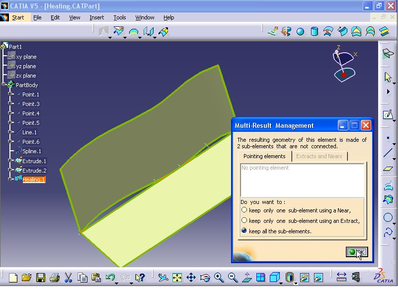
Multi-Result Management window opens. Select the last option which is 'Keep all the sub-elements' and click OK.

Healing.1 is added to the tree, but no changes still happened. The reason is that because the Merging distance (2 mm) is less than maximum distance which is 2.333 mm.

Now double click on Healing.1 from tree. Healing Definition window opens. In Merging distance section enter 2.5 mm.

Click OK.

==========================================================
Disassemble:
In the example, the sketch (Sketch.1) consists of three different sketches.

The problem is that if you want to extrude the sketch all the sketches will be selected.

All the sketches are extruded. But extruding all the sketches is not necessary and we want to extrude only the circle sketch.

To solve the problem, from Operations toolbar click on Disassemble option.

Disassemble window opens. In the window click on All Cells option.

Click OK. As you can see 7 separate curves are created in the specification tree.

In the tree double click on Sketch.1.

The sketcher workbench is active.

Now modify the spline and exit the sketcher workbench.

As you see the previous spline is also remains.

Now select all the lines (Curve.1 to Curve.7) from tree and right click on them and select Delete.


Again click on Disassemble. Disassemble window opens. This time click on 'Domains Only' option then select Sketch.1.

Then click OK. As you see three new curves are added to the tree.

Now each of the sketches are separate and independent. And you can apply operations on sketches separately without affecting each other. For example, click on Extrude command from Surfaces toolbar. Extruded Surface Definition window opens.

Now select the circle for Profile section.

In Direction section right click and select Z Component.

Now the circle sketch is extruded without affecting the rest of the sketches.

Next another example is explained. In this example an spline is created and then by Extrude command is extruded.

Now click on Disassemble. Disassemble window opens. Then select the surface (Extrude.1). In All Cells section number 5 appears. Which indicates that the surface is divided into 5 sections.

Click OK. Now 5 new surfaces are created and added to the tree.

Now right click on one of the surfaces and select Hide/Show option to hide the surface.

As you see the primary surface still exist.

You can delete the previous surface. Right click on the primary surface and select Delete.


==========================================================
Split:
This command is used to divide planes or surfaces into separate planes or surfaces. From Operations toolbar click on Split button. Split Definition window opens.

In Element to cut section select the plane as shown in the figure.

In Cutting elements section select the plane as shown in the figure.

As you see the first plane is split into two planes with contrast colors. The light color section is the section after completing the operation will be omitted.

Now click OK.

Double click on Split.1 from tree. Split Definition window opens. Now select 'Keep both sides' option. The plane is divided into two separate planes without the other sided is omitted.

Selecting 'Intersections computation' will cause the curve resulting from intersection of two planes to be computed and displayed.

Now click OK.

Double click on Split.1 from tree. Split Definition window opens. Now click on Cutting elements section. Then select the third plane as shown in the figure.

This plane also cut the primary plane into two planes. Now click OK.

==========================================================
Trim:
From Operations toolbar select Trim command. Trim Definition window opens. In Mode section there two options: Standard and Pieces. Select Standard from list. Then click on Trimmed elements section. Then click on the two plane as shown in the figure.

Each of these two planes are divided into two planes shown in different colors. After completing the command, the light color planes will be deleted. Click OK.

Again click on Trim command from Operations toolbar. Trim Definition window opens. Then In Trim elements section select the spline as shown in the figure. Then select the straight line.

Now select OK.

The next example:
Click on Trim command from Operations toolbar. Trim Definition window opens. In Trim elements section, select the surfaces as shown in the figure.

Then click on 'Elements to remove' section. Then select the surface as shown in the figure.

Then click OK.

Example:
Click on Trim command from Operations toolbar. Trim Definition window opens. From Mode list select 'Pieces' option. In Trimmed curves section select the inside sections of the first circle as shown in the figure.

Then select the inside sections of the second circle.

Finally select the inside sections of the third circle.

Click OK.

==========================================================
Boundary:
This command extract curves from the edges of a plane or surface. From Operations toolbar click on Boundary command. Boundary Definition window opens. In Surface edge section, select the edge of the plane that you want to extract curves from the selected edge. Then select the edge as shown in the figure.

In Propagation type list select 'No propagation' option. Now the extracted curve is extracted from the selected edge.

Selecting 'Tangent continuity' option, will cause that besides the selected edge, the other edges which are tangent to the edge get selected.

Selecting 'Point continuity' option, will select all the outer edges.

Finally selecting 'Complete boundary' option, will select all the inner and outer edges.

Click OK.

Method 2:
Again click on Boundary command from Operations toolbar. Boundary Definition window opens. Then click on the surface. Now all the edges of the plane are selected and converted.

In Limit 1 section, click on the point as shown in the figure.

Then in Limit 2 section click on the second point as shown in the figure. Close the warning window.

Click OK.

==========================================================
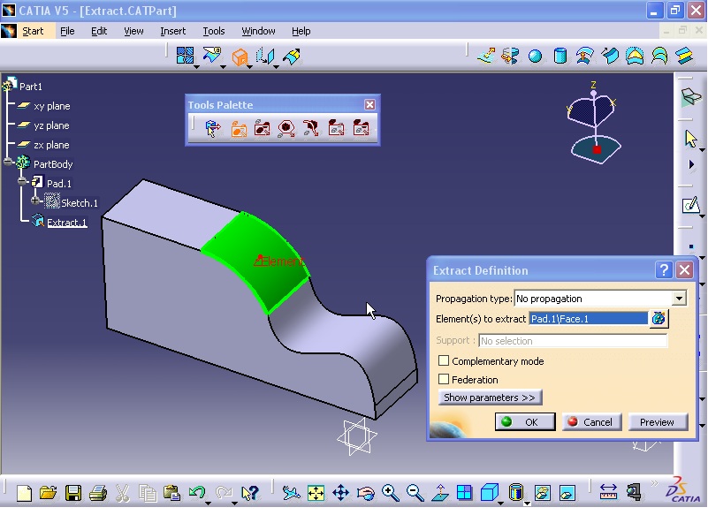
Extract:
From Operations toolbar click on Extract.

Extract Definition window opens. In Propagation type select 'No Propagation' option. In 'Element(s) to extract' section click on the face of the solid as shown in the figure.

From window select 'Complementary mode' option. This will cause that all the surfaces except the selected face to be selected.

Now from Propagation type select 'Tangent continuity' option. This will cause that the surfaces tangent to the selected surface to be selected.

Selecting Point continuity option, will select all the faces adjacent to the selected face.

Select Tangent continuity option and click OK.

The Extract command can be applied to the curves and edges. From Operations toolbar click on Extract command. Extract Definition window opens. Select the edge of the model as shown in the figure.

Click OK.

Next, double click on Extract.2 from tree. Extract Definition window opens.

In Support section select the face as shown in the figure.

Then from Propagation type select 'Point continuity' option.

Click OK.

==========================================================
Translate:
Click on Translate from Operations toolbar.

Translate Definition window opens. From Vector Definition list select 'Direction, distance' option. Then click on the surface.

For Distance section click on the line as shown in the figure.

In Distance section enter 400 mm. Then click on Preview.

Select 'Repeat object after OK' option and click OK.

Object Repetition window opens. In Instance(s) enter 2, uncheck 'Create in a new Body' option.

Click OK.

Again from Surfaces toolbar click on Translate. Translate Definition window opens. From Vector Definition list select 'Point to point' option. In Element section click on the surface. For Start point click on a point.

In End point section click on another point.

The result is shown in the figure.

Click on OK.

Delete the previous translate and click on Translate command again. Translate Definition window opens. From Vector Definition list select Coordinates option. The translation is done in absolute coordinate system. You can define a new coordinate system by right click on Axis System section and select 'Create Axis System'.

Axis System Definition window opens. For Origin click on the point as shown in the figure.

For X axis section click on the line. Click OK to close the window.

Translate Definition window opens again. For Element section click on the surface. Then In X: enter 100 mm, in Y: enter 200 mm, and in Z: enter 300 mm.

Then click OK.

==========================================================
Rotate:
From Operations toolbar click on Rotate.

Rotate Definition window opens. From Definition Mode list select Axis-Angle option. In Element section click on the surface.

In Axis section right click and select Create Line option.

Line Definition window opens. From Line type list select Point-Point option. Now select the two points as shown in the figure.

Click on OK to close the Line Definition window.

Rotate Definition window appears again. Now in Angle section enter 45 degree and click on Preview.

Tick 'Repeat object after OK' option. Then click OK.

Object Repetition window opens. In Instance(s) section enter 2 and click OK.

The result is shown in the figure.

Delete the surfaces and execute Rotate command again. In Rotate Definition window from Definition Mode list select 'Axis-Two Elements' option. For Element section click on the surface. In Axis section select an axis as shown in the figure.

In First element section, right click and select Z Axis option.

In Second element section right click and select X Axis.

The result is shown in the figure.

Click on OK. The surface is rotated 90 degree around X axis.

==========================================================
Symmetry:
From Operations toolbar select Symmetry command.

Symmetry Definition window opens. For Element section select the model as shown in the figure.

For the Reference section select the plane as shown in the figure.

The result is shown in the figure.

If you click on 'Hide/Show initial element' button. The primary element will disappear.

Now click on OK.

Now I will modify the hole in the model. Double click on the Circle sketch from tree.

Circle Definition window opens. Enter 15 mm in Radius section and click OK.

As you see the hole on the symmetry model is modified automatically.


In Elements To Heal section right click and select 'Check Selection' option.

Checker window opens.

Click on Preview. The intersection points are now highlighted.

Now click on OK to close the Checker window. In Parameters tab, there is a section called Merging distance. Enter 2 mm in Merging distance section and click OK.

Multi-Result Management window opens. Select the last option which is 'Keep all the sub-elements' and click OK.
Healing.1 is added to the tree, but no changes still happened. The reason is that because the Merging distance (2 mm) is less than maximum distance which is 2.333 mm.

Now double click on Healing.1 from tree. Healing Definition window opens. In Merging distance section enter 2.5 mm.
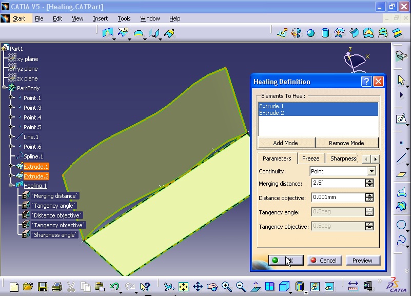
Click OK.

==========================================================
Disassemble:
In the example, the sketch (Sketch.1) consists of three different sketches.

The problem is that if you want to extrude the sketch all the sketches will be selected.

All the sketches are extruded. But extruding all the sketches is not necessary and we want to extrude only the circle sketch.

To solve the problem, from Operations toolbar click on Disassemble option.

Disassemble window opens. In the window click on All Cells option.

Click OK. As you can see 7 separate curves are created in the specification tree.

In the tree double click on Sketch.1.

The sketcher workbench is active.

Now modify the spline and exit the sketcher workbench.

As you see the previous spline is also remains.

Now select all the lines (Curve.1 to Curve.7) from tree and right click on them and select Delete.


Again click on Disassemble. Disassemble window opens. This time click on 'Domains Only' option then select Sketch.1.

Then click OK. As you see three new curves are added to the tree.

Now each of the sketches are separate and independent. And you can apply operations on sketches separately without affecting each other. For example, click on Extrude command from Surfaces toolbar. Extruded Surface Definition window opens.

Now select the circle for Profile section.

In Direction section right click and select Z Component.

Now the circle sketch is extruded without affecting the rest of the sketches.

Next another example is explained. In this example an spline is created and then by Extrude command is extruded.

Now click on Disassemble. Disassemble window opens. Then select the surface (Extrude.1). In All Cells section number 5 appears. Which indicates that the surface is divided into 5 sections.

Click OK. Now 5 new surfaces are created and added to the tree.

Now right click on one of the surfaces and select Hide/Show option to hide the surface.

As you see the primary surface still exist.

You can delete the previous surface. Right click on the primary surface and select Delete.


==========================================================
Split:
This command is used to divide planes or surfaces into separate planes or surfaces. From Operations toolbar click on Split button. Split Definition window opens.

In Element to cut section select the plane as shown in the figure.

In Cutting elements section select the plane as shown in the figure.

As you see the first plane is split into two planes with contrast colors. The light color section is the section after completing the operation will be omitted.

Now click OK.

Double click on Split.1 from tree. Split Definition window opens. Now select 'Keep both sides' option. The plane is divided into two separate planes without the other sided is omitted.
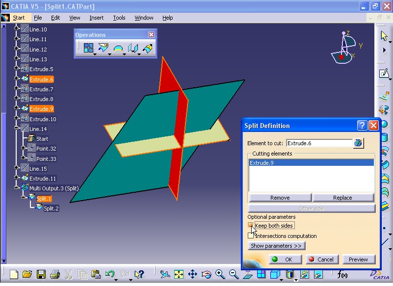
Selecting 'Intersections computation' will cause the curve resulting from intersection of two planes to be computed and displayed.

Now click OK.

Double click on Split.1 from tree. Split Definition window opens. Now click on Cutting elements section. Then select the third plane as shown in the figure.

This plane also cut the primary plane into two planes. Now click OK.

==========================================================
Trim:
From Operations toolbar select Trim command. Trim Definition window opens. In Mode section there two options: Standard and Pieces. Select Standard from list. Then click on Trimmed elements section. Then click on the two plane as shown in the figure.

Each of these two planes are divided into two planes shown in different colors. After completing the command, the light color planes will be deleted. Click OK.

Again click on Trim command from Operations toolbar. Trim Definition window opens. Then In Trim elements section select the spline as shown in the figure. Then select the straight line.

Now select OK.

The next example:
Click on Trim command from Operations toolbar. Trim Definition window opens. In Trim elements section, select the surfaces as shown in the figure.

Then click on 'Elements to remove' section. Then select the surface as shown in the figure.

Then click OK.

Example:
Click on Trim command from Operations toolbar. Trim Definition window opens. From Mode list select 'Pieces' option. In Trimmed curves section select the inside sections of the first circle as shown in the figure.

Then select the inside sections of the second circle.

Finally select the inside sections of the third circle.

Click OK.

==========================================================
Boundary:
This command extract curves from the edges of a plane or surface. From Operations toolbar click on Boundary command. Boundary Definition window opens. In Surface edge section, select the edge of the plane that you want to extract curves from the selected edge. Then select the edge as shown in the figure.

In Propagation type list select 'No propagation' option. Now the extracted curve is extracted from the selected edge.

Selecting 'Tangent continuity' option, will cause that besides the selected edge, the other edges which are tangent to the edge get selected.

Selecting 'Point continuity' option, will select all the outer edges.

Finally selecting 'Complete boundary' option, will select all the inner and outer edges.

Click OK.

Method 2:
Again click on Boundary command from Operations toolbar. Boundary Definition window opens. Then click on the surface. Now all the edges of the plane are selected and converted.

In Limit 1 section, click on the point as shown in the figure.

Then in Limit 2 section click on the second point as shown in the figure. Close the warning window.

Click OK.

==========================================================
Extract:
From Operations toolbar click on Extract.

Extract Definition window opens. In Propagation type select 'No Propagation' option. In 'Element(s) to extract' section click on the face of the solid as shown in the figure.
From window select 'Complementary mode' option. This will cause that all the surfaces except the selected face to be selected.

Now from Propagation type select 'Tangent continuity' option. This will cause that the surfaces tangent to the selected surface to be selected.

Selecting Point continuity option, will select all the faces adjacent to the selected face.

Select Tangent continuity option and click OK.

The Extract command can be applied to the curves and edges. From Operations toolbar click on Extract command. Extract Definition window opens. Select the edge of the model as shown in the figure.

Click OK.

Next, double click on Extract.2 from tree. Extract Definition window opens.

In Support section select the face as shown in the figure.

Then from Propagation type select 'Point continuity' option.

Click OK.

==========================================================
Translate:
Click on Translate from Operations toolbar.

Translate Definition window opens. From Vector Definition list select 'Direction, distance' option. Then click on the surface.

For Distance section click on the line as shown in the figure.

In Distance section enter 400 mm. Then click on Preview.

Select 'Repeat object after OK' option and click OK.

Object Repetition window opens. In Instance(s) enter 2, uncheck 'Create in a new Body' option.

Click OK.

Again from Surfaces toolbar click on Translate. Translate Definition window opens. From Vector Definition list select 'Point to point' option. In Element section click on the surface. For Start point click on a point.

In End point section click on another point.

The result is shown in the figure.

Click on OK.

Delete the previous translate and click on Translate command again. Translate Definition window opens. From Vector Definition list select Coordinates option. The translation is done in absolute coordinate system. You can define a new coordinate system by right click on Axis System section and select 'Create Axis System'.

Axis System Definition window opens. For Origin click on the point as shown in the figure.

For X axis section click on the line. Click OK to close the window.

Translate Definition window opens again. For Element section click on the surface. Then In X: enter 100 mm, in Y: enter 200 mm, and in Z: enter 300 mm.

Then click OK.

==========================================================
Rotate:
From Operations toolbar click on Rotate.

Rotate Definition window opens. From Definition Mode list select Axis-Angle option. In Element section click on the surface.

In Axis section right click and select Create Line option.

Line Definition window opens. From Line type list select Point-Point option. Now select the two points as shown in the figure.

Click on OK to close the Line Definition window.

Rotate Definition window appears again. Now in Angle section enter 45 degree and click on Preview.

Tick 'Repeat object after OK' option. Then click OK.

Object Repetition window opens. In Instance(s) section enter 2 and click OK.

The result is shown in the figure.

Delete the surfaces and execute Rotate command again. In Rotate Definition window from Definition Mode list select 'Axis-Two Elements' option. For Element section click on the surface. In Axis section select an axis as shown in the figure.

In First element section, right click and select Z Axis option.

In Second element section right click and select X Axis.

The result is shown in the figure.

Click on OK. The surface is rotated 90 degree around X axis.

==========================================================
Symmetry:
From Operations toolbar select Symmetry command.

Symmetry Definition window opens. For Element section select the model as shown in the figure.

For the Reference section select the plane as shown in the figure.

The result is shown in the figure.

If you click on 'Hide/Show initial element' button. The primary element will disappear.

Now click on OK.

Now I will modify the hole in the model. Double click on the Circle sketch from tree.

Circle Definition window opens. Enter 15 mm in Radius section and click OK.

As you see the hole on the symmetry model is modified automatically.

=========================================================
Surface Design (Scaling - Shape Fillet - Edge Fillet - Variable Fillet - Multi-Result Management)
Scaling:
From Transformations toolbar click on Scaling command.

Scaling Definition window opens. For Element section select the surface. In Reference section click on the point as shown in the figure.

In Ration section enter 2 and click on Preview.

Click on Reference section. Right click on the Reference and select ZX Plane.

The model now looks like the below image.

Now again right click on Reference and select XY Plane.

The model now looks like the below image.


In Ration section enter 2 and click on Preview.

Click on Reference section. Right click on the Reference and select ZX Plane.

The model now looks like the below image.

Now again right click on Reference and select XY Plane.

The model now looks like the below image.

Click on OK.

==========================================================
ShapeFillet:
From menu click on Start - Shape - Generative Shape Design.

From menu click on Insert - Operations - ShapeFillet.

Fillet Definition window opens. In Fillet type section select BiTangent Fillet option. For Support 1 select the surface as shown in the figure.

For Support 2 click on the second surface.

By selecting Radius option, you can define the radius of the fillet. Click on Preview to see the result.

Chordal option defines the distance of between the end edges of the fillet.

From Extremities section select Smooth option and click on Preview.

From Extremities section select Straight option and click on Preview.

From Extremities section select Maximum option and click on Preview.

From Extremities section select Minimum option and click on Preview.

Now select 'Trim support 1' and click on Preview. Now part of the first surface is transparent. This means that after ending the command this part of plane will be omitted.

Now select 'Trim support 2'.

Click on OK.

Another method of ShapeFillet:
From menu click Insert - Operations - ShapeFillet.

Fillet Definition window opens. From Fillet type list select TriTangent Fillet option. For Support 1 select the surface as shown in the figure.

For Support 2 select the surface as shown in the figure.

For 'Support to remove' section select the surface as shown in the figure.

Now click on Preview.

Selecting Trim support 1 and Trim support 2 will delete the extra surfaces after filleting. After selecting these two options click on Preview.

From Extremities list select Minimum option and click OK.


Tritangent Fillet:
From menu click Insert - Operations - Tritangent Fillet.

Tritangent Fillet Definition window opens. In Faces to fillet section select the two faces as shown in the figure.

In Face to remove section select the middle surface as shown in the figure.

Now click on OK.

==========================================================
Edge Fillet:
From menu click Insert - Operations - Edge Fillet.

Edge Fillet Definition window opens. For 'Object(s) to fillet' section select the edge as shown in the figure. In Radius section define the radius of the fillet.

Now click on Preview.

Now click on OK.

Delete the previous fillet surface and again execute the Edge fillet command. In Edge Fillet Definition window, for Object(s) to fillet section select the two planes as shown in the figure.

Click on OK.

Example 2:
The model is created as shown in the figure. A new plane intersects the fillet surface.

Double click on EdgeFillet.2. This fillet was created previously. Edge Fillet Definition window opens. Click on More button. Now Edge Fillet Definition window extends. Click on Limiting element(s). Now click on the new plane as shown in the figure.

Now click on OK. The plane acts as a boundary and fillet is done for one side of the edge.


==========================================================
Variable Fillet:
In the example two planes are extruded and joined together and converted to a unit plane.

Otherwise it is impossible to select the edge. Therefore the planes must join together.

Also before executing the Variable Fillet command, you need to create some points with different coordinates on the edge. Now click on Point from Wireframe toolbar. Point Definition window opens.

From Point type list select 'On curve' option. Then select the edge as shown in the figure.

Select 'Ratio of curve length' option. Enter 0 in Ratio section and click on Preview.

Click OK.

Again click on Point from Wireframe toolbar. Point Definition window opens. Make sure that 'On curve option from Point type is selected. For Curve section select the edge.

In Ratio section enter 0.2 and click on Preview.

And then click on OK.

Repeat above procedure to create more points with ratios of 0.4, 0.6, 0.8, and 1 respectively. The final order of the points on the edge is shown in the figure.

Now from menu click on Insert - Operations - Variable Fillet.

'Variable Radius Fillet Definition' window opens. Enter 1 mm in Radius box. For Edge(s) to fillet section select the edge as shown in the figure.

In Points section select all the points which were created previously.

Now at each point you can define the radius relevant to each point by double clicking on R 1 on each point as shown in the figure.

Enter 2 mm for the radius of the point and click OK. 'Variable Radius Fillet Definition' window opens. Again double click on the next point. Parameter Definition window opens. Enter 3 mm in the Radius box and click OK. Repeat the procedure for rest of the points by entering radius of 4 mm, 5 mm, 6 mm. Finally after entering the last radius of the point, as 'Variable Radius Fillet Definition' window is open, in Variation section you can define the method of radius variation. If you select Linear, the variation will be linear and if you select Cubic option, the variation will be like curve shape. Select Linear option and click on Preview.

Click on OK.

==========================================================
Multi-Result Management:
Make sure you are in Generative Shape Design Workbench. From menu click on Insert - Wireframe - Parallel Curve.

Parallel Curve Definition window opens. For Curve section click on the plane as shown in the figure.

In Constant section enter 2 mm. For Support section click on the plane.


Click on OK. Multi-Result Management window opens. The reason why this window is opened, is that the new curve consists of two separate curves and software wants to know whether you want to keep the curves or delete them.

One of the options in the window is 'Keep all the sub-elements'. Selecting this option will keep all the curve elements. Select this option and click OK.


Now from specification tree, double click on Parallel.1.

Parallel Curve Definition window opens. Then click on OK. Multi-Result Management window opens.

Now select 'Keep only one sub-element using a Near' option and click on OK.

Near Definition window opens. For Reference Element section select part of the model as shown in the figure.

Then click on OK. The nearest section of the curve is kept and the other part is deleted.

Example 2:
From Surfaces toolbar click on Combine command. Combine Definition window opens. Select the two curves as shown in the figure. Then uncheck 'Nearest solution' option. And Normal is selected from Combine type. Click on OK.

Multi-Result Management window opens. Because result of the execution of the combine command is two separate curves.

Now select 'Keep only one sub-element using an Extract' option.

Click on OK. Extract Definition window opens. For Element(s) to extract section click on the curve as shown in the figure.

Click on OK.

=========================================================
All 21 Types of Sweep surface commands In CATIA I Generative shape Design:
==========================================================
its best practice
ReplyDelete