Surface Design (Axis System - Geometrical Set):
One of the workbenches in CATIA is Wireframe and Surface Design. The workbench is located in Start - Mechanical Design - Wireframe and Surface Design.
One of the workbenches in CATIA is Wireframe and Surface Design. The workbench is located in Start - Mechanical Design - Wireframe and Surface Design.

New Part window opens. Enter a new name for the part name and click OK.

Now you are in Wireframe and Surface Design workbench.

To activate toolbars, right click on any toolbar and select Wireframe option.

Wireframe toolbar appears.

There are two ways to operate the commands: First, you can click on commands on toolbar. For example click on Point command.

Point Definition window opens.

Or from Menu click Insert - Wireframe and then select the appropriate command.

After creating the points, lines and polylines, the surface encompassing all the wireframes and lines need to be created. This can be done through the Surfaces toolbar. Right click on any toolbar and select Surfaces option.

Surfaces toolbar appears.

To operate the Surfaces commands there two ways: First you can click on any command from toolbar or you can select the command from Menu - Insert - Surfaces.

After creating the surface, some operations such as trim, extend, binding, etc need to be done. To do this, first right click on any toolbar and select Operations toolbar.
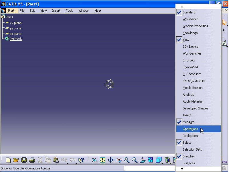
Operations window appears.

You can operate the Operations command by either clicking on any command from toolbar or From Menu - Insert - Operations.

Another workbench which is used to create surfaces is called Generative Shape Design. From Start click Shape - Generative Shape Design.

Now Generative Shape Design workbench is active.
==========================================================
Axis System:
By this command we can define the coordinate system. To operate this command from Menu click Insert - Axis System...

Axis System Definition window opens.

You can operate this command by clicking on Axis System icon from Tools toolbar.

To define the origin you need to select a point. For example click On any corner of a cube.

To define X axis you need to select a line or an edge which shows the direction of the X axis.

The same as above can be done for Y and Z axis.

By clicking on OK, the Axis System is added to the specification tree.

You can view the specifications of the axis tree by expanding the axis tree.

Now from Menu click Tools - Options.

Options window opens. From left column select Parameters and Measure. Then from right column click on Knowledge tab.

In Parameter Tree View section, tick With Value option. Then click OK.

From specification tree you can see the values of X, Y, and Z for Axis System.

Now click on Compass and drag it until it is placed on the top face of the cube.


Then rotate the compass. You can see that the cube rotates.

Again operate Axis System command.

Axis System Definition window opens. The new axis system with a name of Axis System.2 is added to the Specification tree. Direction of the new axis system is parallel to the axis of compass.

Now in Origin box right click and select Create Midpoint option.

Then click on the line in the graphic area. The midpoint of the line is selected. Then click OK to close the window.

Again operate Axis System from Tools toolbar. Axis System Definition window opens.

From Axis System Type select Axis rotation option.

Then click on the point at the beginning of the line as the origin of the axis system.

Then select the line as the direction of the X axis.

As the Reference box is active, click on the face of the cube. This face is the reference face.

Then change the value of the angle. The new axis system is created. Then click OK to close the window.

Expand the Axis System 3 from specification tree.

Double click on AxisRotation option. Edit Parameter window opens. You can modify the axis system by changing the rotation angle.

==========================================================
Geometrical Set:
geometrical Sets are like Windows folders. Use them to get structure into your part. Geometrical Sets contains: Wireframe like lines, points, curves, surfaces, sketches,...
To create a geometrical set, from Menu click Insert - Geometrical Set...

Insert Geometrical Set window appears. In Name section you can define a name. For example enter Set-01. Click OK to close the window.

Set-01 is added to the specification tree.

Now create another geometrical set and name it geometrical set 2.

Again operate Geometrical Set command from Insert menu, and create a geometrical set with name of sub-set-01. Then from Father list select set-01 and click OK.

As you can see in specification tree, the new sub-set-01 is a subset of set-01.

Now click on sketch icon.

Then select yz plane from specification tree.

Now you are in sketcher workbench.

Then draw a circle in graphical area.

Next, exit from the sketcher.

As you can see the sketch is appeared under sub-set-01.

Now from specification tree right click on set-01 and select Define In Work Object option.

As you can see a line appears under the set-01 geometrical set. It means that set-01 is active.

Now from wireframe toolbar click on Line command.

Then select the origin of the coordinate system for Point 1.

Then right click on Point 2 and select Create Point option.

Point Definition window appears. Enter X = 50mm and click OK.

The line is now created. Then click OK on Line Definition window to close the window.

The line.1 is appeared under set-01 set.

You can also change the geometrical set and replace it with another geometrical set. For example, first right click on sub-set-01 and select sub-set-01 object.

Then from the menu select Change Geometrical Set... option.

Change geometrical set window opens. From Destination select set-02 and click OK.

Now sub-set-01 is subset of set-02.

To delete a subset, just right click on set-01 and select Delete.

In some cases where a geometrical set is subset of another geometrical set, the subset geometrical set can be deleted without its content get deleted. For example, right click on sub-set-01 and select sub-set-01 Object. Then if you select Remove Geometrical Set option, only the set will be removed not its contents.

As you see the contents of the sub-set-01 is moved to the subset of set-02.

=======================================================
Surface Design (Point - Line):
Point:There are different ways to define a point. To create lines, planes you need first create reference points. To create point, click on Point command from Wireframe toolbar. Point Definition window opens.

In Point Type section there is a list that contains different methods of creating points.

To begin from Point Type list select Coordinates.

By entering values in X, Y, and Z the point can be defined.

In Point from Reference section, a point can be selected as the origin of the point. And the coordinates of the X, Y, and Z are defined referred to the new point. Then click OK to close the window.

The next option from Point type is 'On curve'.

By using this method you can define the point on any curve. First to select the curve click on it.

From Distance to reference select 'Distance on curve' option. The point is defined as distance from the origin.

The calculation of the distance between the origin and the point is done through two methods: Geodesic and Euclidean. The Geodesic option calculates the distance between the point on any part of the curve and the origin.

Selecting Euclidean option, calculates the least distance between reference point and a point on curve.

By clicking on Reverse Direction, will cause the origin of the distance calculation move to the other end of the point (reversed). Click OK to close the window.

Again click on Point command from Wireframe toolbar. Then select the curve. This time select Ratio of curve length option. This option will define the relative distance from the whole length of the curve.

By clicking on Middle point, the point is located at the middle of the curve.

Next point type method is 'On plane'.

To define a point you need first select a plane. For example select zx plane.

By entering vertical and horizontal values for H and V you can define the point.

The next method to define a point is 'On surface'. By this method you can create a point on a surface.

For example, first click on a surface on which you want to create a point.

Then activate the Direction section by clicking on it. Then select a line as a direction.

Then activate the Point from Reference. Then select the point as shown in the figure.

Then select Coarse option from Dynamic positioning. Then click on the arrow by the Distance box increase the distance. As you see, the point is defined by picturing the point located on the direction line to the surface. Click OK to close the window.

This time instead of selecting 'Coarse' option select 'Fine'. The point is defined on the surface freely by moving the mouse on the surface without defining any direction.


The next method is 'Circle/Sphere/Ellipse center'

By this method you can define a point at the center of a circle, Sphere, or Ellipse. For example select the spherical surface which created previously. Click OK to close the window.

Again use the previous method and this time select a circle. The point is defined at the center of the circle.

The next method is 'Tangent on curve'.

For the Curve section select a curve.

Then click on a line for Direction. You will see that three points are created on the curve. These points are points that defined from intersection of lines which are parallel to the direction line and are tangent on the curve.

The last method of point definition is 'Between'. In this method you need to select two points in space so the point is defined between the two points on the straight line connecting these two points. In Ratio you can enter a value to define the point in relative to either points.

==========================================================
Line:
In this section the methods of creating lines are considered. To activate line command, from Wireframe toolbar, click on 'Line' command. Line Definition window opens.

In Line type section there is a list that through application of commands in this list you can create line.

Expand the list and select 'Point-Point' option. You need to define two points. For example, the first point is selected.

Then select the second point.

Then a line is created. As you see the beginning and end of the line is marked with Start and End.

You can increase the length of the line by clicking on the Start or End arrow button.

You can also increase or decrease the length of the line by gripping the arrows at each end and dragging them.

Another section in this window is 'Support'. While the Support section is active click on the surface.

The shape of the straight line is changed and now is converted to a curve which is positioned on the surface.

The next method from Line type list is 'Point-Direction'.

To create a line using this method, you need to select a point and also a direction to which the line will be parallel. For example select a point.

Then select a line as a direction.

As you see the line pass the point and is parallel to the direction line.

The next method is 'Angle/Normal to curve'.

First select a curve.

Then select a point.

This line pass the point and makes an angle of 45 degree with the direction of the line tangent to the curve.

You can change the length and angle of the line by holding the grips and moving them.

The next method is 'Tangent to curve'.

First select a curve.

For Element 2 select another curve.

As you see three lines are created. Three lines are tangent to the curves. The orange line will be remained after finishing the command.

By clicking on Next solution button you can select any of lines.

By clicking on OK you can select and create the final line.

The next method is 'Normal to surface'.

First select a surface.

Then select a point. This line pass through the point and is perpendicular to the surface.

The final method is 'Bisecting'.

The created line is the bisector of two lines which are co-planar. Select the first line.

Then select the second line.

The created line is the bisector of two lines.

=========================================================
Surface Design (Polyline - Axis - Plane):
Polyline:Polyline consists of number of lines connected together in spatial. In this post six points are created in different coordinates. From Wireframe toolbar click on Polyline.

Polyline Definition window opens. Then select Points 1 to point 6 from specification tree respectively.

In Radius section you can define the radius of the fillets for each corner.

Then click OK to finish the execution.

Now execute Sketch command.

Then select the sketch plane as shown in figure.

Create a circle which its center is the origin of coordinate system.

Use Constraint command to define the diameter of the circle as 5mm.

Then click OK to finish the execution.

Then exit the Sketcher workbench.

From Start click Mechanical Design - Part Design.

In specification tree right click on PartBody and select 'Define In Work Object' option.

Then execute 'Rib' command.

Rib Definition window opens. In Profile section select the Circle drawn previously.

And for Center curve select the Polyline.

Finally by clicking on Preview and OK, end the execution.

Now we want to create a tube out of the solid profile. First double click on Sketch.1. The sketch workbench is active now.

Execute Circle command and create another circle with the same center as the previous circle.

Then use Constraint command to create the circle with diameter of 6mm.


Next exit the Sketcher workbench.

As you see the model is converted to a tube profile with thickness of 0.5mm.

==========================================================
Axis:
Click on Axis command from Wireframe toolbar. Axis Definition window opens.

In Element section select the circle.

In Direction section the direction of the axis is defined. In this section right click and select X Component.

From Axis type list select Aligned with reference direction.

Selecting Normal to reference direction, will create an axis normal to the direction reference.

Selecting Normal to circle option, will create an axis which is perpendicular to the plane passing the circle.


Click OK to end the execution of Axis command and Axis.1 is added to the specification tree.

Again execute Axis command and this time in Element section select the Ellipse.

From Axis type list select Major axis.

Select Minor axis option from Axis type.

Finally select Normal to ellipse option.


Again execute Axis command from Wireframe. Axis Definition window opens. For Element section select the surface. This surface is produced through Revolve command.


Click OK to end the execution of Axis command. Axis.3 is added to the specification tree.

==========================================================
Plane:
There are different methods to create a plane in geometrical space. From Wireframe toolbar click on Plane command. Plane Definition window opens.

The methods of creating plane are listed in Plane type section.

Select the first method which is 'Offset from plane'. In Reference section select a plane the new new plane is parallel to the reference plane with a distance. You can change the distance between these two planes by increasing or decreasing the value of Offset.

Tick 'Repeat object after OK' option. Then click OK.

Object Repetition window opens. In Instances section 2 is typed. Click OK.


The next method is 'Parallel through point'. For Reference section select a plane.

The Point section is active. Select a point.

The new plane pass through the point and is parallel to the reference plane.

The next method is 'Angle/Normal to plane'. For Rotation axis select a line.

For Reference section select a plane.

In Angle section the angle between new plane and the reference plane is defined.

By clicking on Normal to plane button, the new plane becomes perpendicular to the reference plane.


The next method is 'Through three points'. Select the first point.

Select the second point.

And select the third point.

The new plane which goes through three points is created.

By clicking on OK the new plane is created.

The next method is 'Through two lines'. For Line 1 select a line or edge.

For the Line 2 select another line.

The new plane which goes through two lines is created.

The next method is 'Through point and line'. First select a point.

For Line section select a line.

The new plane goes through the point and the line. Click OK to end the Plane command.

The next method is 'Through planar curve'. This method is used to create a plane which goes through a curve or a 2D sketch. Select a curve.


The next method is 'Normal to curve'. The new plane is perpendicular to the curve. Select a curve.

Then we need to select a point through which the plane pass and is perpendicular to the curve. The default is the Middle point of the curve. To change the point select a new point.

The new plane goes through the point and is perpendicular to the curve.

The next method is 'Tangent to surface'. The new plane goes through a point and is tangent to a surface. For Surface section select a surface.

Now select a point.

The new plane goes through the point and is tangent to the surface.

The next method is 'Equation'. The equation of a plane in geometrical space is Ax + By + Cz = D. By entering values for A, B, C, and D you can create a plane.

In Point section by selecting a point D parameter will be defined automatically and the new plane goes through the point. Now select a point.

The new plane is created.


The name of the points are appeared in the Points list. You can modify the points by selecting a point and then applying Remove or Replace commands.

For example by removing one of the points from list the position of the new plane changes. Click OK to end the Plane command.

========================================================
Surface Design - (Arc and Circle - Corner - Connect Curve - Spline - Helix - 3D Curve Combine command):
Arc and Circle:
First click on Circle command from Wireframe toolbar. Circle Definition window opens.

Click on Circle type list and select Center and radius option.

Select a point as the center of the circle.


Then for Support section click on the surface of a plane on which the circle will be created.


Enter a number in Radius.

In Circle Limitations you can create the whole circle or a partial circle.

If you select the left button (Creates a partial circle), it will create a partial circle not complete circle. By clicking on this button two options, Start and End are added.


You can also define the partial circle by clicking on the handles and dragging them.

Another option is called Axis Computation.This will calculate and create the axis of the circle normal to the surface on which the circle is situated.

By clicking on OK the circle or the partial circle is created.

The next method to create circle is Center and point. Click on Circle command from Wireframe toolbar and from list select Center and point. Click on a point as the center.

Then select a point. This point will be situated on circumference of the circle. This circle goes through the point.

For support section click on a plane or surface on which the circle will be situated.

A preview of the circle is shown.

By clicking OK the circle is created.

The next method to create circle is Two points and radius. Click on Circle command and select Two points and radius. In this method by defining two points and radius the circle can be created.

First select two points respectively.

Then select a plane for support. A preview of two circles is shown.

In Circle Limitations two options are added. By using these options you can create a partial circle.

A preview of the partial circle is created.

By clicking on OK the circle is created.

The next method to create a circle is Three points. Click on Circle command and select Three points option. Select three points respectively. The circle goes through three points. This circle is also situated on the plane which is defined by three points.

Then for support click on a surface.

The circle will lay on the surface.

The next method is Center and axis. Click on Circle command and select Center and axis option. Select a line as the axis of the circle.

Then select a point. The circle goes through this point.

You can define the radius of the circle by entering a value in Radius box.

By clicking on OK the circle is created.

The next method is Bi-tangent and radius. Click on Circle and select this option. The circle is tangent to two lines. Enter 50 for the radius of the circle then for Element 1 and 2 select two lines respectively. You can see a preview of the circle.

Increase or decrease the radius. You see that the size of the circle changes.

The next method is Bi-tangent and point. Click on Circle and select this option. The circle is tangent to the curves and will goes through the point. Select a curve as Element 1. Then select the second curve for Curve 2. Then select the point on the curve. You can see the preview of the circle.

By clicking on the partial circle button the bottom part of the circle which is tangent to the curves and is between two curves is displayed.

Now Trim Element 1 and 2 are active. If you select them the extra bit of the curves which is after the contact between the circle and the curves, will be omitted.

Then click OK to see the results.

The next method to create a circle is Tritangent. In this method the circle is tangent to three curves. Click on Circle and select this option. Select three curves respectively for Element 1, 2, and 3.

By clicking on the button for whole circle a complete circle is displayed.

Click OK to see the results.

The last method is Center and tangent. Click on Circle and select this option. For Center Element select a point. For Tangent Curve select the edge of the plane.

Click OK to see the results.

==========================================================
Corner Command:
This command is used to fillet the intersection of lines.

Corner Definition window opens.

From Corner Type select Corner on Support option. This option is used for co-planar situation. Uncheck the Corner on Vertex option. Then select two lines which are co-planar and intersect each other. As you see there four modes of corner created through intersection of two lines. By clicking on Next Solution button you can approach to any of the modes.

You can also change the radius of the curve by entering a value in Radius box.

Activate Trim element 1 and 2 then click OK and see the results.

Again click on Corner command and again select Corner on Support option. For Element 1 and 2 select the two curves on the surface. As you still the OK and Preview buttons are grey and are not active. The reason is that these two curves are located on a non-flat surface.

To complete the command, as the Support box is active, select the non-flat surface.

Now the at the intersection point, four corners are created.


Now click on OK and see the result.


Again click on Corner command. Select Corner on Support option and activate Corner on Vertex option. Then select a vertex.


Now click on OK to see the result.

Finally the Corner command is applied to two 3D curve which don't intersect each other and are not co-planar.

Click on Corner button. From Corner Type select 3D Corner option. Then deactivate Corner on Vertex option. Select two curves as Element 1 and 2.

Click on OK and you will see the result.

==========================================================
Connect Curve command:
From menu click Insert - Wireframe - Connect Curve...

Connect Curve Definition window opens. This window consists of two sections: First Curve and Second Curve.

Activate Point from First Curve by clicking on it. Then select the point as shown in the figure. By selecting the point, the curve is also selected automatically.

Then activate Point from Second Curve and select the second point on the second curve. By selecting the point, the curve is also selected automatically. Now you can see a preview of the connecting curve.

Select Trim elements option and click OK. Final result is shown in figure below.


==========================================================
Spline Command:
By this command you can create a curve which goes through some points. Spline Definition window opens.

Select the points respectively. Use Close Spline option to close the spline. In Tangent Direction, select a point and then select a line. The line tangent to the curve at the point will be parallel to the selected line.

Finally click OK to close the window.

==========================================================
Helix Command:
From Wireframe toolbar click Helix button.

Helix Curve Definition window opens.

For Starting Point select a point.

For Axis select a line.

You can see a preview of the helix.

You can modify the helix by changing the value of Pitch.

Increase the value of Height and see the result.

From Orientation select Clockwise.

Increase value of Starting Angle.

You can create an inclined helix by increasing the value of Taper Angle.

From Way list select Outward.

Click OK to see the final result.

3D Curve Combine command:
In CATIA we can't draw 3D curve directly. First you have to draw two sketches from two different views of curve you want to make including either front, top, back or bottom view then you have to use combine option to get 3D curve. You will find Combine command in Generative Shape Design workbench.

In Circle Limitations you can create the whole circle or a partial circle.

If you select the left button (Creates a partial circle), it will create a partial circle not complete circle. By clicking on this button two options, Start and End are added.


You can also define the partial circle by clicking on the handles and dragging them.

Another option is called Axis Computation.This will calculate and create the axis of the circle normal to the surface on which the circle is situated.

By clicking on OK the circle or the partial circle is created.

The next method to create circle is Center and point. Click on Circle command from Wireframe toolbar and from list select Center and point. Click on a point as the center.

Then select a point. This point will be situated on circumference of the circle. This circle goes through the point.

For support section click on a plane or surface on which the circle will be situated.

A preview of the circle is shown.

By clicking OK the circle is created.

The next method to create circle is Two points and radius. Click on Circle command and select Two points and radius. In this method by defining two points and radius the circle can be created.

First select two points respectively.

Then select a plane for support. A preview of two circles is shown.

In Circle Limitations two options are added. By using these options you can create a partial circle.

A preview of the partial circle is created.

By clicking on OK the circle is created.

The next method to create a circle is Three points. Click on Circle command and select Three points option. Select three points respectively. The circle goes through three points. This circle is also situated on the plane which is defined by three points.

Then for support click on a surface.

The circle will lay on the surface.

The next method is Center and axis. Click on Circle command and select Center and axis option. Select a line as the axis of the circle.

Then select a point. The circle goes through this point.

You can define the radius of the circle by entering a value in Radius box.

By clicking on OK the circle is created.

The next method is Bi-tangent and radius. Click on Circle and select this option. The circle is tangent to two lines. Enter 50 for the radius of the circle then for Element 1 and 2 select two lines respectively. You can see a preview of the circle.

Increase or decrease the radius. You see that the size of the circle changes.


By clicking on the partial circle button the bottom part of the circle which is tangent to the curves and is between two curves is displayed.

Now Trim Element 1 and 2 are active. If you select them the extra bit of the curves which is after the contact between the circle and the curves, will be omitted.

Then click OK to see the results.

The next method to create a circle is Tritangent. In this method the circle is tangent to three curves. Click on Circle and select this option. Select three curves respectively for Element 1, 2, and 3.

By clicking on the button for whole circle a complete circle is displayed.

Click OK to see the results.

The last method is Center and tangent. Click on Circle and select this option. For Center Element select a point. For Tangent Curve select the edge of the plane.

Click OK to see the results.

==========================================================
Corner Command:
This command is used to fillet the intersection of lines.

Corner Definition window opens.

From Corner Type select Corner on Support option. This option is used for co-planar situation. Uncheck the Corner on Vertex option. Then select two lines which are co-planar and intersect each other. As you see there four modes of corner created through intersection of two lines. By clicking on Next Solution button you can approach to any of the modes.

You can also change the radius of the curve by entering a value in Radius box.

Activate Trim element 1 and 2 then click OK and see the results.

Again click on Corner command and again select Corner on Support option. For Element 1 and 2 select the two curves on the surface. As you still the OK and Preview buttons are grey and are not active. The reason is that these two curves are located on a non-flat surface.

To complete the command, as the Support box is active, select the non-flat surface.

Now the at the intersection point, four corners are created.


Now click on OK and see the result.


Again click on Corner command. Select Corner on Support option and activate Corner on Vertex option. Then select a vertex.


Now click on OK to see the result.

Finally the Corner command is applied to two 3D curve which don't intersect each other and are not co-planar.

Click on Corner button. From Corner Type select 3D Corner option. Then deactivate Corner on Vertex option. Select two curves as Element 1 and 2.

Click on OK and you will see the result.

==========================================================
Connect Curve command:
From menu click Insert - Wireframe - Connect Curve...

Connect Curve Definition window opens. This window consists of two sections: First Curve and Second Curve.

Activate Point from First Curve by clicking on it. Then select the point as shown in the figure. By selecting the point, the curve is also selected automatically.

Then activate Point from Second Curve and select the second point on the second curve. By selecting the point, the curve is also selected automatically. Now you can see a preview of the connecting curve.

Select Trim elements option and click OK. Final result is shown in figure below.


==========================================================
Spline Command:
By this command you can create a curve which goes through some points. Spline Definition window opens.

Select the points respectively. Use Close Spline option to close the spline. In Tangent Direction, select a point and then select a line. The line tangent to the curve at the point will be parallel to the selected line.

Finally click OK to close the window.

==========================================================
Helix Command:
From Wireframe toolbar click Helix button.

Helix Curve Definition window opens.

For Starting Point select a point.

For Axis select a line.

You can see a preview of the helix.

You can modify the helix by changing the value of Pitch.

Increase the value of Height and see the result.

From Orientation select Clockwise.

Increase value of Starting Angle.

You can create an inclined helix by increasing the value of Taper Angle.

From Way list select Outward.

Click OK to see the final result.

3D Curve Combine command:
In CATIA we can't draw 3D curve directly. First you have to draw two sketches from two different views of curve you want to make including either front, top, back or bottom view then you have to use combine option to get 3D curve. You will find Combine command in Generative Shape Design workbench.
=======================================================
Surface Design (Projection - Intersection - Spine - Spiral - Extremum - Parallel Curve - 3D Curve Offset - Combine):
Projection:
Click on Projection from Wireframe toolbar. Projection Definition window opens.

From Projection type select Normal option.

In Projected section select a curve.

In Support section select the surface.

Click on Preview button you will see the result.

Click on OK. The projected line will be created.

The second method to create projected line is Along a direction. From Projection type select Along a direction option. In Projected section select the curve.

In Support section select the surface.

In Direction section select a line.

To define Direction you can also right click on Direction section and select one of the coordinate system axis (X, Y, Z).

Nearest Solution option creates a curve which has the minimum distance from the main curve.

Click on OK. The curve will be created.

==========================================================
Intersection:
From Wireframe toolbar click on Intersection command. Intersection Definition window opens.

In First Element section click on the curve.

In Second Section click on the second curve.

In Result section if you choose Curve, the common section between the two curves will be considered. If you choose point, the points resulted from intersection of curves will be created.

Select Curve option and click OK. If you see a Warning message, close it.

Intersect.1 is added to the specification tree and the curve is created.

To use the next intersect method, from Wireframe toolbar click on Intersect. In First Element select the surface.

In Second Element select the cube.

In Result section if you choose Contour option, the curve, resulted from intersection of cube and the surface will be created. By clicking on Preview you will see the result.

But if you select Surface option from Result section, the result of intersection of the surface and the cube will be a flat plane.

Click on OK to see the result.

Again click on Intersection command from Wireframe toolbar. Then for First Element and Second Element select the two surfaces respectively.

Click on Preview. The result will be a curve.

Click on OK to see the result.

In the following explanation of intersection methods, from Wireframe toolbar click on Intersection. In First Element click on the line.

In Second Element click on the second line. Note that these two lines are not intersected.

By clicking on 'Extend linear supports for intersection' the lines will be extended to intersect each other. Select the 'Extend linear supports for intersection' option for both First Element and Second Element. Click on Preview to see the result. As a result of intersection of two lines, a point in created.

Click OK to end the command.

Next two lines are non co-planar. Again click on Intersection. In First Element select the line. For Second Element select the second line.

Tick 'Intersect non co-planar line segments' option. By selecting the option, the shortest line, connecting these two non co-planar lines, will be calculated and the middle point of the shortest line will be considered as the intersection point.

Click OK to see the result.

To explain the next method, click on Intersection. In First Element and Second Element select the plane and surface respectively. Then click on Preview to see the result.

Now select 'Extrapolate intersection on first element' option. Again click on Preview. The curve is extended from both sides.

By clicking on OK the curve is created.

==========================================================
Spine:
This command is used to create 3D curves. First make sure you are in Generative Shape Design workbench. Then from menu click Insert - Wireframe - Spine.

Spine Curve Definition window opens. By this command you can create a 3D curve which is normal to some planes or closed profiles. As the Section/Plane is active, select the planes respectively. The curve is perpendicular to each plane.

Click on the point as Start point.

Click OK to end the command.

Again click on Spine command. Then first click on the closed profile. Then click on the planes respectively.

Click OK to end the command.

==========================================================
Spiral:
Make sure you are still in Generative Shape Design workbench.

Then from Wireframe toolbar click on Spiral command.

Spiral Curve Definition window opens. In Support section select the plane.

Click on Center point section to make it active. Then select the point.

In Reference direction section right click and select X Component.

In Start radius, you can define the primary radius of the spiral. Enter 5mm. There are three methods to define the spiral. Angle & Radius - Angle & Pitch - Radius and Pitch.

Select Angle & Radius option. Enter 30 degree in End angle. Enter 15 in End Radius. In Revolutions section, define the number of revolution of the spiral.

From Type section select Angle & Pitch option.

Finally, from Type list select Radius & Pitch option. End radius and Pitch need to be defined.

Now click on OK to see the result.

==========================================================
Extremum:
Make sure you are still in Generative Shape Design workbench.

By this command, the points with minimum and maximum height on a curve or plane, considering a direction, can be defined.
Now from menu click Insert - Wireframe - Extremum.

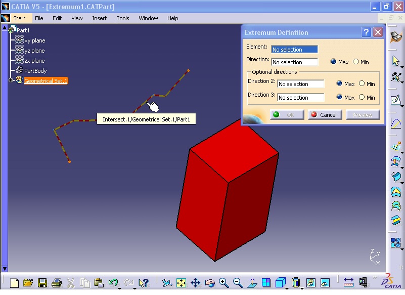
Extremum Definition window opens. In Element section you can select a spline or plane. First select the curve.

In Direction section, right click and select X Component.

If the Max option is ticked, the point with maximum height in X direction will be defined.

Select Min to define the minimum height.

Click OK to end the command.

Again click on Extremum command. This time select the face of the cube as shown in the figure.

In Direction section right click and select Z Component.

The top face of the cube has the maximum height in Z direction.

Next in Direction 2 right click and select Y Component.

Click OK to see the result. The edge of the cube has the maximum height in both Z and Y directions.

Double click on Extremum.2. Extremum Definition window opens.

In Direction 3 right click and select X Component.

Now the point at the corner of the cube is defined. This point has the maximum height in X, Y, and Z direction.

==========================================================
Parallel Curve:
Make sure you are still in Generative Shape Design workbench.

From Wireframe toolbar click on Parallel Curve command. Parallel Curve Definition window opens.

In Curve section select the curve.

In Support section, select the plane as shown in the figure. In Constant section you can define the distance of the new curve from the first curve.

Click on Preview to see the result. The new curve is created on the support plane.

In Support section right click and select Clear Selection option.

By gripping the handle and dragging it, the curve will move out of the plane in anywhere in the space.

If you want the curve to be defined, with variable distance from the primary curve, you need to click on Law ... button. Law Definition window opens. Then select Linear option. In Start value and End value enter 0.5 mm and 2 mm respectively and close the window.

Then click on Preview button to see the result.

Now click on Reverse Direction button then Preview.

Now click on OK.

Again click on Parallel Curve and in Curve section select the curve as shown in the figure.

Then by clicking on the Reverse Direction button change the direction of the curve creation.

Then in Constant box enter 5 mm. Click on Preview to see the result.

Now from Parallel corner type, select Round.

Click on Preview button.

Click OK.

==========================================================
3D Curve Offset:
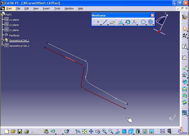
From Wireframe toolbar click on 3D Curve Offset.

3D Curve Offset Definition window opens. In Curve section select the curve as shown in the figure.

In Pulling direction box right click and select Y Component.

Click Preview button to see the result.

In Offset section you can define the distance between the two curves.

Click OK to see the final result.

==========================================================
Combine:
Make sure you are in Generative Shape Design workbench.

From menu click Insert - Wireframe - Combine. With this command you can create a curve, which is created by combination of Extrusion and Intersection of two spatial curves.

Combine Definition window opens. From Combine type select Normal. In Curve 1 select the curve as shown in the figure.

Then for Curve 2 select the second curve.

Click OK to see the result.

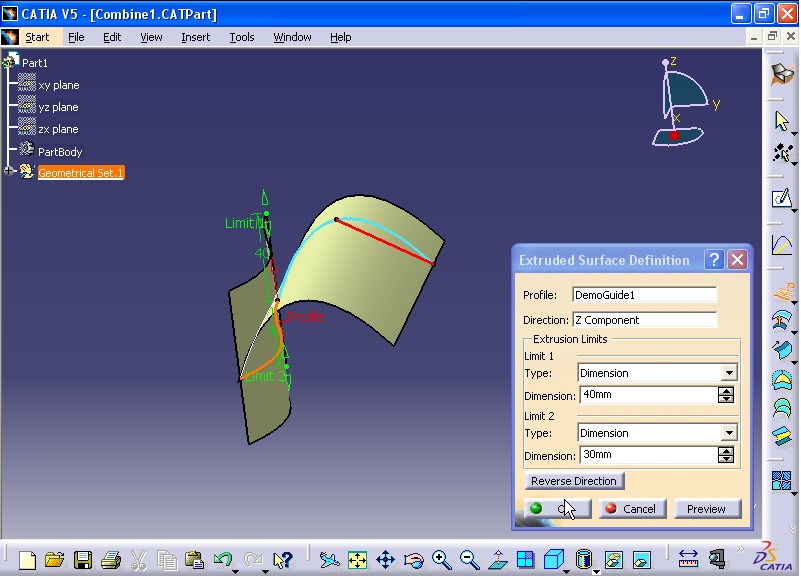
To see the instruction of the Combine command, click on Extrude command.

Extruded Surface Definition window opens. In Profile section select the curve as shown in the figure.

In Direction section right click and select X Component.

The first surface is created in X direction.

Click OK.

Again click on Extrude command and in Profile section select the curve as shown in the figure.

In Direction section right click and select Z Component.

The second curve is created in Z direction.

Click OK. As you see the intersection of the two surfaces exactly lay on the created curve resulted from Combine command.

Again click on Combine command and select the second option which is Along direction.

Another Combine Definition window opens. In Curve 1 section select the curve as shown in the figure.

In Curve 2 section select the curve as shown in the figure.

In Direction 1 section, select the line as shown in the figure.

And in Direction 2 section right click and select X Component.

Click OK to see the result. This curve is the result of intersection between the extrusion of the the first curve in the direction of the line and extrusion of the second curve in the direction of X axis.


To define Direction you can also right click on Direction section and select one of the coordinate system axis (X, Y, Z).

Nearest Solution option creates a curve which has the minimum distance from the main curve.

Click on OK. The curve will be created.

==========================================================
Intersection:
From Wireframe toolbar click on Intersection command. Intersection Definition window opens.

In First Element section click on the curve.

In Second Section click on the second curve.

In Result section if you choose Curve, the common section between the two curves will be considered. If you choose point, the points resulted from intersection of curves will be created.

Select Curve option and click OK. If you see a Warning message, close it.

Intersect.1 is added to the specification tree and the curve is created.

To use the next intersect method, from Wireframe toolbar click on Intersect. In First Element select the surface.

In Second Element select the cube.

In Result section if you choose Contour option, the curve, resulted from intersection of cube and the surface will be created. By clicking on Preview you will see the result.

But if you select Surface option from Result section, the result of intersection of the surface and the cube will be a flat plane.

Click on OK to see the result.

Again click on Intersection command from Wireframe toolbar. Then for First Element and Second Element select the two surfaces respectively.

Click on Preview. The result will be a curve.

Click on OK to see the result.

In the following explanation of intersection methods, from Wireframe toolbar click on Intersection. In First Element click on the line.

In Second Element click on the second line. Note that these two lines are not intersected.

By clicking on 'Extend linear supports for intersection' the lines will be extended to intersect each other. Select the 'Extend linear supports for intersection' option for both First Element and Second Element. Click on Preview to see the result. As a result of intersection of two lines, a point in created.

Click OK to end the command.

Next two lines are non co-planar. Again click on Intersection. In First Element select the line. For Second Element select the second line.

Tick 'Intersect non co-planar line segments' option. By selecting the option, the shortest line, connecting these two non co-planar lines, will be calculated and the middle point of the shortest line will be considered as the intersection point.

Click OK to see the result.

To explain the next method, click on Intersection. In First Element and Second Element select the plane and surface respectively. Then click on Preview to see the result.

Now select 'Extrapolate intersection on first element' option. Again click on Preview. The curve is extended from both sides.

By clicking on OK the curve is created.

==========================================================
Spine:
This command is used to create 3D curves. First make sure you are in Generative Shape Design workbench. Then from menu click Insert - Wireframe - Spine.

Spine Curve Definition window opens. By this command you can create a 3D curve which is normal to some planes or closed profiles. As the Section/Plane is active, select the planes respectively. The curve is perpendicular to each plane.

Click on the point as Start point.

Click OK to end the command.

Again click on Spine command. Then first click on the closed profile. Then click on the planes respectively.

Click OK to end the command.

==========================================================
Spiral:
Make sure you are still in Generative Shape Design workbench.

Then from Wireframe toolbar click on Spiral command.

Spiral Curve Definition window opens. In Support section select the plane.

Click on Center point section to make it active. Then select the point.

In Reference direction section right click and select X Component.

In Start radius, you can define the primary radius of the spiral. Enter 5mm. There are three methods to define the spiral. Angle & Radius - Angle & Pitch - Radius and Pitch.

Select Angle & Radius option. Enter 30 degree in End angle. Enter 15 in End Radius. In Revolutions section, define the number of revolution of the spiral.

From Type section select Angle & Pitch option.

Finally, from Type list select Radius & Pitch option. End radius and Pitch need to be defined.

Now click on OK to see the result.

==========================================================
Extremum:
Make sure you are still in Generative Shape Design workbench.

By this command, the points with minimum and maximum height on a curve or plane, considering a direction, can be defined.
Now from menu click Insert - Wireframe - Extremum.

Extremum Definition window opens. In Element section you can select a spline or plane. First select the curve.
In Direction section, right click and select X Component.

If the Max option is ticked, the point with maximum height in X direction will be defined.

Select Min to define the minimum height.

Click OK to end the command.

Again click on Extremum command. This time select the face of the cube as shown in the figure.

In Direction section right click and select Z Component.

The top face of the cube has the maximum height in Z direction.

Next in Direction 2 right click and select Y Component.

Click OK to see the result. The edge of the cube has the maximum height in both Z and Y directions.

Double click on Extremum.2. Extremum Definition window opens.

In Direction 3 right click and select X Component.

Now the point at the corner of the cube is defined. This point has the maximum height in X, Y, and Z direction.

==========================================================
Parallel Curve:
Make sure you are still in Generative Shape Design workbench.

From Wireframe toolbar click on Parallel Curve command. Parallel Curve Definition window opens.

In Curve section select the curve.

In Support section, select the plane as shown in the figure. In Constant section you can define the distance of the new curve from the first curve.

Click on Preview to see the result. The new curve is created on the support plane.

In Support section right click and select Clear Selection option.

By gripping the handle and dragging it, the curve will move out of the plane in anywhere in the space.

If you want the curve to be defined, with variable distance from the primary curve, you need to click on Law ... button. Law Definition window opens. Then select Linear option. In Start value and End value enter 0.5 mm and 2 mm respectively and close the window.

Then click on Preview button to see the result.

Now click on Reverse Direction button then Preview.

Now click on OK.

Again click on Parallel Curve and in Curve section select the curve as shown in the figure.

Then by clicking on the Reverse Direction button change the direction of the curve creation.

Then in Constant box enter 5 mm. Click on Preview to see the result.

Now from Parallel corner type, select Round.

Click on Preview button.

Click OK.

==========================================================
3D Curve Offset:
From Wireframe toolbar click on 3D Curve Offset.

3D Curve Offset Definition window opens. In Curve section select the curve as shown in the figure.

In Pulling direction box right click and select Y Component.

Click Preview button to see the result.

In Offset section you can define the distance between the two curves.

Click OK to see the final result.
==========================================================
Combine:
Make sure you are in Generative Shape Design workbench.

From menu click Insert - Wireframe - Combine. With this command you can create a curve, which is created by combination of Extrusion and Intersection of two spatial curves.

Combine Definition window opens. From Combine type select Normal. In Curve 1 select the curve as shown in the figure.

Then for Curve 2 select the second curve.

Click OK to see the result.

To see the instruction of the Combine command, click on Extrude command.

Extruded Surface Definition window opens. In Profile section select the curve as shown in the figure.

In Direction section right click and select X Component.

The first surface is created in X direction.

Click OK.

Again click on Extrude command and in Profile section select the curve as shown in the figure.

In Direction section right click and select Z Component.

The second curve is created in Z direction.
Click OK. As you see the intersection of the two surfaces exactly lay on the created curve resulted from Combine command.

Again click on Combine command and select the second option which is Along direction.

Another Combine Definition window opens. In Curve 1 section select the curve as shown in the figure.

In Curve 2 section select the curve as shown in the figure.

In Direction 1 section, select the line as shown in the figure.

And in Direction 2 section right click and select X Component.

Click OK to see the result. This curve is the result of intersection between the extrusion of the the first curve in the direction of the line and extrusion of the second curve in the direction of X axis.

==========================================================
Surface Design (Extrude - Revolve - Sphere - Cylinder - Offset - Variable Offset - Fill - Multi-Sections - Blend):
What is interior and exterior trim design in automotive?
The interior trim of an automobile consists of many different types of parts ranging from seating to plastic parts.The design of Automotive Interior and Exterior plastic components is called Trims. It will be done in CATIA Generative Shape Design (GSD) workbench.
The plastic components that you see inside the car is Interior. Ex: Dashboard, Instrument Panel, Doors, seating and pillars.
The plastic components that you see outside of a car are Exterior. ex: bumper, light assembly, hoods.
==========================================================
CATIA ICEM:
CATIA ICEM is the ultimate technology, combining the precision and quality of Class-A surface design with the power of CATIA. Taking benefits of both best 3D tools “CATIA and ICEM”. CATIA ICEM Shape Design provides the most advanced mathematics and comprehensive suite of tools to reach the highest quality of surface, by integrating the ICEM technology into CATIA. It allows creating, editing and analysing any complex, aesthetic and ergonomic shapes to the highest Class-A surface quality.
CATIA ICEM drives the Class-A Design Innovation:
CATIA ICEM brings the power of CATIA within the 3D EXPERIENCE platform and allows 3D data to be shared with any other applications and then streamline design and engineering collaboration. Starting from basic inputs such as design sketches or point-clouds from physical prototypes, bring your design to Class-A surface quality and ready for manufacturing.
- Integrated Best-in-Class ICEM Surfacing technology
- Unified Surfacing solution: Power | Precision | Flexibility
- Streamline Design & Engineering collaboration
- Keep Global Design Network Connected
CATIA ICEM covers the entire development process chain, allowing software-based development to minimise the reliance on physical prototype and standalone renderers in the early development phases.
CATIA ICEM is the ultimate surface-modelling platform, combining the precision and quality of Class-A surface design with the power of CATIA.
=======================================================
Case Study: Wireframe creation


=========================================================
Wireframe and Surface Design:

Wireframe Toolbar

Connect Curve:
Select connect curve from Insert menu and Wireframe.

Connect Curve Definition appears.

1). Activate point from First Curve. And select the point on the first curve. The curve will be selected automatically as well.


2). Activate Point from Second Curve section and click on the second point on the second curve. The curve will be selected automatically as well.

Then click on OK.

===========================================================
Multi-Sections Surface:


As you notice two sections have 4 vertices each and one has 5 vertices. Therefore there will be a problem when creating the surfaces. Select three sections and click on Preview.
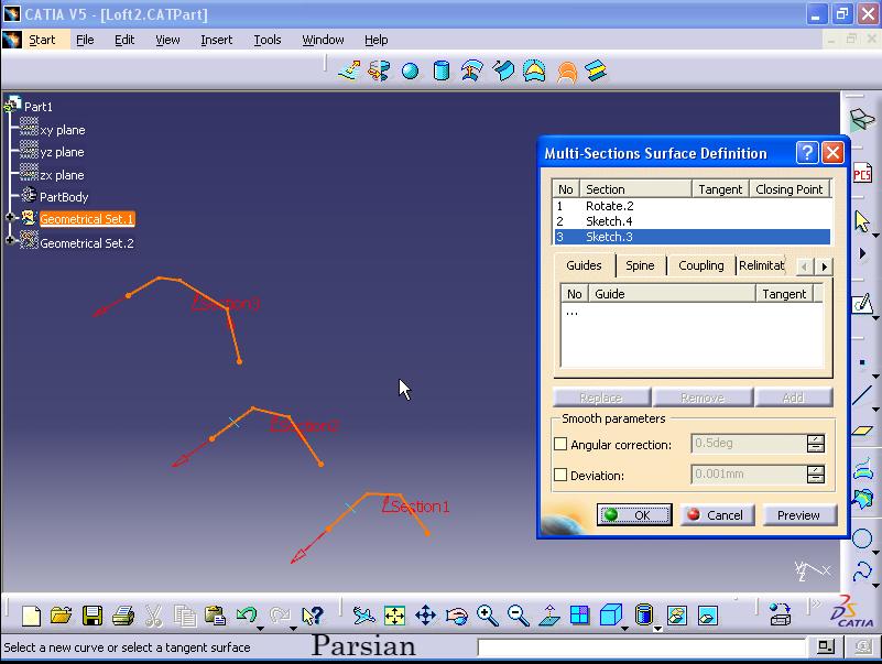

To solve this problem enter Coupling tab. Click on Add. Coupling window appears.

1) Select the point on first section.

2) Select the second point on the middle section curve.

These two points have already been created by point command.
3). Select the third point on the third section curve. The coupling window closes automatically. Coupling 1 is created.

4). Click on Add again. Select first point on the first section curve.

5). Select the second point as below.

6) Select the third point as below. Coupling 2 is created.

7) Click on Add again. Select the first point from first section curve.

8). Select the second point from the second section curve.

9). Select the third point from third section curve.

Now click on Preview. The created surface is smooth and have a better quality than previous surface.

Surface modeling:
Extrude:
By this command you can create surface by extruding line or curves (giving height). In Surfaces toolbar, click on Extrude button.

Extruded Surface Definition window opens. In Profile section select the line, or curve.

In Direction section right click and select X Component.

You can define the amount of height for both sides of the surface by entering values in dimensions for Limit 1 and 2. Then click Preview to see the results.

Now click on Direction box and right click. Select the Y Component option.

Click Preview to see the results.

Now from Type for Limit 1 select Up-to element option.

In Up-to element section you can select an edge, plane, vertex to define the limitation of the height of the surface. Now in Up-to element section right click and select Create Plane option.

Plane Definition window opens. In Reference section select yz plane from specification tree. In Offset section enter value of 40 mm and click OK.

Extruded Surface Definition window opens. Click OK to close the window and see the result.

Extrude.1 is added to the specification tree. Expand Extrude.1. Limit 2 and Plane.1 (The plane was created in previous step) are added to the tree.

To modify the plane, double click on Plane.1. Plane Definition window opens. Change the Offset value to 45 mm and click OK.


==========================================================
Revolve:
Click on Revolve from Surfaces toolbar.

Revolution Surface Definition window opens. For Profile section click on the spline.

In Revolution axis right click and select Z Axis option.

The surface is created through revolution of the spline around the z axis.

In Angle 1 and 2, you can define the revolution angles. Enter 150 and 30 degrees in Angle 1 and 2 respectively.

Right click in Angle 1 and 2 and select Lock option.

Now you are not able to change the angles.

You can define Revolution axis by selecting an edge of the cube. Click in Revolution axis and select the edge of the cube.

You van edit the parameters of the revolution. Now Revolute.1 is added to the tree. Expand the tree and double click on Angle.1.Edit Parameter window opens. Enter 130 degree and click OK.


==========================================================
Sphere:
From Surfaces toolbar click on Sphere.

Sphere Surface Definition window opens. In Center section select the origin of coordinate system as center of the sphere. In Sphere radius section you can define the radius of the sphere.

In Sphere Limitations, you can define the sphere to be complete or partially displayed.
Partial sphere:

Complete sphere:

In Sphere Limitations click on the left button (Partial sphere). You can define and change the Parallel Start Angle and End Angle.

Now click on OK to end the sphere operation.

You can edit the parameters of the sphere from specification tree.

Cylinder:
From menu click Start - Mechanical Design - Wireframe and Surface Design.

From Surfaces toolbar click on Cylinder.

Cylinder Surface Definition window opens. In Point section right click and select Create Point option.

Point Definition window opens. Define the point as the origin of coordinate system (0,0,0) and click OK.

In Direction section define the direction of the cylinder. To define Direction from specification tree click on zx plane. The direction of the cylinder is Y axis which is normal to the zx plane.

In Parameters section you can define Radius, Length 1 and 2.

Now in Direction right click and select X Component option.

Now the cylinder is created in X direction.

Finally click on OK.

You can also modify the cylinder parameters from specification tree.

Offset:
From Surfaces toolbar click on Offset command.

Offset Surface Definition window opens. In Surface section select the surface.

In Offset section you can define the distance between the second surface and the primary surface.

Click on Preview to see the result.

Click on Reverse Direction button it will change the direction of the second surface.

If you tick Both sides option, two surfaces will be created at both sides of the primary surface.

Tick 'Repeat object after OK'. By enabling this option, you van create instances of the primary surface.

Click on OK. Object Repetition window opens. Enter 2 in the Instances box then uncheck 'Create in a new Body' option and click OK.

Multiple instances of the primary surface is created.

==========================================================
Variable Offset:
The distance between the second surface and the primary surface is not constant. First create a Geometrical Set. From menu click Insert - Geometrical Set...

Insert Geometrical Set window opens. Enter 01 in Name box and click OK.

Next click on Sketch button.

Then click on yz plane in specification tree.

Click on Line command and draw two parallel lines.

Exit the workbench.

From menu click Insert - Operations - Disassemble...

Disassemble window opens. Now select the sketch.

From Disassemble window select 'All Cells' option. Then click OK.

Now the sketch is transformed into two separate lines with Curve.1 and Curve.2 names.

Now from specification tree, right click on Sketch.1 and select Hide/Show option. This will hide the Sketch.1.

Next from Wireframe toolbar click on Connect Curve.

Connect Curve Definition window opens. Then click at the end and start of the two lines respectively.


These two points are inserted in First Curve and Second Curve sections.

From Continuity in both sections, select Tangency options and click OK.

Now the two curves are connected together. The connector line is tangent to two lines at their connection points.

Next from Surfaces toolbar, click on Extrude.

Extruded Surface Definition window opens. Now select the left side curve.

Then in Direction section right click and select X Component option.

A surface from the curve in X direction is created.

Enter 50 mm in Limit 1 Dimension section and click OK.

The curve is created.

Then repeat the above procedure for the middle and last curves. From Surfaces toolbar click on Extrude. Extruded Surface Definition window opens. Click on the middle curve. In Direction section right click and select X Component.

Then click OK.

Again from Surfaces toolbar click on Extrude. Extruded Surface Definition window opens. Select the last curve. In Direction section right click and select X Component option.

Then click OK.

Finally, three surfaces with Extrude.1, Extrude.2 and Extrude.3 are created.

Next I want to give different colors to the surfaces. Right click on one of the surfaces and select Properties.

Properties window opens. Open the Color list and select a color and click OK.

Now you can see the effects.

Repeat the above procedure for the rest of the surfaces. At the end the surfaces will look like image below.

Now I want to integrate all the surfaces and make a unit surface. From menu click Insert - Operations - Join.

Join Definition window opens. Select all the surfaces and click OK.

Now one unit surfaces is created.

Next right click on Join.1 and select Hide/Show option. This will hide the curve.

The curve is hidden.

Select Extrude.1, Extrude.2 and Extrude.3 from specification tree and right click and select Hide/Show option.

This will show the surfaces.

From menu click Insert - Surfaces - Variable Offset.

Variable Offset Definition window opens. Click in Base Surface section and from specification tree select Join.1 which was created in previous step.

In Parameters tab for Sub-Part to Offset section select the Extrude.1, Extrude.2, and Extrude.3 surfaces.

You can enter a value for each surface. In Offset section enter 25 mm for Extrude.1. For Extrude.3 enter 38 mm. Select Extrude.2 and from Offset list select Variable option. This will cause the offset to be calculated as variable not constant. Because the middle surface is supposed to be connecting the other two surfaces. Now click on Preview button.

Click on Reverse Direction button.

Now click on OK.

If you expand Variable Offset.1 and double click on Offset.Extrude.1 Edit Parameter window opens. You can change the amount of parameter.

==========================================================
Fill:
From Surfaces toolbar click on Fill command.

Fill Surface Definition window opens. In Boundary and in Curves section, first click the curve.

Then click on the next curve.

Then click on the next curve.

Finally click on the last curve.

Now click on Preview button. To execute the fill command it is necessary to select the curves in order.

Activate Passing point section. Now click on a point. The surface will pass through the point.

Then click on Preview button. The surface is transformed and now pass through the point.

Click on OK.

==========================================================
Multi-Sections:
From Surfaces toolbar click on Multi-Sections Surface.

Multi-Sections Surface Definition window opens. In Section select the first curve.

Then select the second and third curves.

Now click on Preview button.

Now right click on the middle curve. Then select Remove option.

Then click on Preview.

To add the curve, right click on first curve and select Add After option.

Now click on the middle curve.

Click on Preview.

Finally click on OK.

------------------------------------------------
Different method of Multi-Sections:
From Surfaces toolbar click on Multi-Sections Surface. Multi-Sections Surface Definition window opens. In Section first click on the curve as shown in the figure.

Then click on the second curve.

As you can see the directions of the arrows are not the same and consistent.

Therefore the execution of the command is not possible. It can be proved by clicking on Preview. An error message appears.

Click on OK.

To solve the problem, just click once on the arrow to change the direction of the arrow.

Again click on Preview.

In the next section, the guide curves are considered. As you see the surface does not pass through any guide curves. To select guide curves, first click on Guide tab. Then click on Guide section. Now select the first curve.

Then select the second curve.

Now click on Preview. Now the surface pass through the guide lines.

As the Guide section is active, select the other curve.

Then select the last curve.

Again click on Preview.

Now click on OK.

--------------------------------------------------------
Different Multi-Sections method:
From Surfaces toolbar click on Multi-Sections Surface. Multi-Sections Surface Definition window opens.
Considering from the model, the first two curves have four vertices. Whereas the third curve has 5 vertices. This will cause problem when creating a surface which will pass through the curves.

In Section, select all the curves.

Now click on Preview. The surface is warped and need be corrected.

To solve the problem, click on Coupling tab. Now click on Add button.

Then click the point on the first curve.

Then select the point on the second curve.

Finally click the vertex on the third curve.

The Coupling window closes automatically. A green line which connects the three points together is appeared. Coupling1 is added to the Coupling list.

Next again click on Add button. Coupling window opens. Select the vertex from the first curve.

Then click the vertex on the second curve.

Then click the vertex on the third curve.

Now Coupling2 is added to the Coupling list and a green path is created.

Then repeat the above procedure for the remaining vertices of the curves. Click on Add button. Coupling window opens. Now select the vertex on the first curve.

Click the vertex on the second curve.

Then click the vertex on the third curve.

The Coupling 3 is added to the Coupling list and a green path is created.

Now click on Preview. The surface is more smooth and better quality.

Finally click on OK.

==========================================================
Blend:
From Surfaces toolbar click on Blend command. Blend Definition window opens.

In First curve section click on the line as shown in the figure.

In First support section click on the plane as shown in the figure.

In second curve section, click on the line as shown in the figure.

In Second support section, click on the plane as shown in the figure.

In Basic tab, from First continuity list select Point option. Also from Second continuity list select Point option. Now click on Preview. The surface is flat plane. This is due to selecting Point option.

Now from First continuity list select Tangency option and click on Preview. The surface is tangent on the first support plane.

Then from Second continuity list select Tangency option and click on Preview.

Now select Curvature option from First and Second continuity list. Now to see the better result change the view to front mode. From menu click on View - Named Views...

Named Views window opens. Select front option from list. Click OK.

Now click on Preview.


The other option in the Blend Definition window is Trim first and second support option. This is for trimming the extra sections of the surface or plane. As you see, the extra section of the first support plane is sticking out. To do this tick the 'Trim first support' option.

Now click on OK.

=========================================================
No comments:
Post a Comment