Constraints control the geometric relationships, such as parallel or tangent, between sketch entities. Sketch constraints are visible only while editing the sketch.
Constraints are automatically created or inferred, while sketching. Constraint symbols dynamically display as you sketch, and the cursor snaps to that position. For example, if a tangent constraint displays while sketching a line, the line preview stays tangent as you move the cursor in that direction.
Constraint is a kind of relation between the entities (which you are creating in the sketch) and the references. All the elements of a sketch are called sketch entities. Similarly for creating any sketch entities, you need to refer to some already existing entities, and these are called reference entities.
Geometric constraint is a relationship that forces a limitation between one or more Geometric elements. Dimensional constraint is a constraint, whose value determines the geometric object measurement.
In this post constraint is discussed. First activate sketcher in CATIA. First click Start - Mechanical Design - Sketcher.

Then click on XY plane to choose the plane sketch.

Click on Profile in Profile toolbar.

Create a sketch consists of lines and curves.

Click on part of sketch and hold the mouse button and drag the mouse. You can see that the sketch moves and changes. It means the relations between sketch features have not been fully defined. Therefore we need to create constraints to prevent it.

The Constraint toolbar is used to create sketch constraints.

From Tools menu click Options. Options window opens. From left column click on Sketcher and then click on SmartPick... button.


Delete the previous sketch and click on Line button in Profile toolbar.

Create a line. By clicking on the line and dragging the line you can see the line can move and change easily.

Again click on Line button and then activate Geometrical Constraints from Sketch tools toolbar.

Then create a line. You can see that the letter H is appeared on top of the line which means this line is horizontally constrained.

This time draw a inclined line. As you see by moving the mouse closer to the first line a dotted line appears. By clicking on the screen a letter O appears.

This letter represents the Coincidence constraint.

This time draw a line which is parallel to the previous line. A parallel sign appears.


Again create a line which is perpendicular to the previous line. As you see the perpendicular sign appears as you move the mouse toward the line.


Now click on Circle and create a circle. As you move the mouse toward the line the tangent sign appears. This means tangential between circle and the line.


Again click on Circle. And move the mouse towards the center of the previous circle. The sign of concentricity constraint appears.


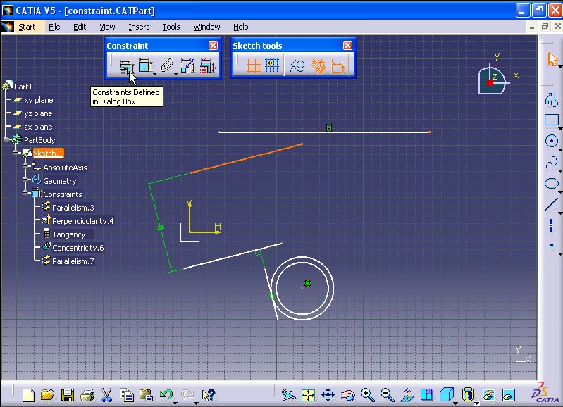
All the created constraints can be seen in Specification Tree.

Constraint Toolbar:
First delete all the geometrical constraints created in previous steps.
For example I want to delete the horizontal constraint. From specification tree click on Constraints option. Then right click on the letter H which represents the horizontal constraint. Then select Center graph option.

The Parallelism.1 is selected. The reason why the parallelism is selected because this line is parallel and horizontal to the X axis of the coordinate.

Right click on the Parallelism.1 and select delete.

Now select the line and activate Constraints Defined in Dialog Box. To activate this first you have to activate Geometrical constraints from Sketch Tools toolbar.


Constraint Definition window opens. Select Horizontal option. You will see that the line becomes horizontal. Click OK to close the window.


Now delete the coincidence constraint between two lines.

By pressing down Ctrl key from keyboard select the line and the end point of the other line.

Then activate Constraints Defined in Dialog Box.

Constraint Definition window opens. Now select Coincidence option. As you see the constraint coincidence is created between the line and the end point of the other line.

For the parallelism, delete the parallelism constraint between the two lines.

Now by pressing down Ctrl key, select the two lines. Then activate Constraints Defined in Dialog Box. Constraint Definition window opens.

Select Parallelism option from window and click OK.

The two lines become parallel.

For perpendicularity, first delete this constraint from specification tree.

Then pick the lines and activate Constraints Defined in Dialog Box. Constraint Definition window opens.

Select Perpendicular option and click OK. The line is now perpendicular to the other line.

Then click on XY plane to choose the plane sketch.

Click on Profile in Profile toolbar.

Create a sketch consists of lines and curves.

Click on part of sketch and hold the mouse button and drag the mouse. You can see that the sketch moves and changes. It means the relations between sketch features have not been fully defined. Therefore we need to create constraints to prevent it.

The Constraint toolbar is used to create sketch constraints.

From Tools menu click Options. Options window opens. From left column click on Sketcher and then click on SmartPick... button.

Another window opens. Smart Pick is a method of making elements constrained in CATIA. You can choose which constraints to be made automatically by CATIA. Click OK to close the window.

Delete the previous sketch and click on Line button in Profile toolbar.

Create a line. By clicking on the line and dragging the line you can see the line can move and change easily.

Again click on Line button and then activate Geometrical Constraints from Sketch tools toolbar.

Then create a line. You can see that the letter H is appeared on top of the line which means this line is horizontally constrained.

This time draw a inclined line. As you see by moving the mouse closer to the first line a dotted line appears. By clicking on the screen a letter O appears.

This letter represents the Coincidence constraint.

This time draw a line which is parallel to the previous line. A parallel sign appears.


Again create a line which is perpendicular to the previous line. As you see the perpendicular sign appears as you move the mouse toward the line.


Now click on Circle and create a circle. As you move the mouse toward the line the tangent sign appears. This means tangential between circle and the line.


Again click on Circle. And move the mouse towards the center of the previous circle. The sign of concentricity constraint appears.


All the created constraints can be seen in Specification Tree.

Constraint Toolbar:
First delete all the geometrical constraints created in previous steps.
For example I want to delete the horizontal constraint. From specification tree click on Constraints option. Then right click on the letter H which represents the horizontal constraint. Then select Center graph option.

The Parallelism.1 is selected. The reason why the parallelism is selected because this line is parallel and horizontal to the X axis of the coordinate.

Right click on the Parallelism.1 and select delete.

Now select the line and activate Constraints Defined in Dialog Box. To activate this first you have to activate Geometrical constraints from Sketch Tools toolbar.


Constraint Definition window opens. Select Horizontal option. You will see that the line becomes horizontal. Click OK to close the window.


Now delete the coincidence constraint between two lines.

By pressing down Ctrl key from keyboard select the line and the end point of the other line.

Then activate Constraints Defined in Dialog Box.
Constraint Definition window opens. Now select Coincidence option. As you see the constraint coincidence is created between the line and the end point of the other line.

For the parallelism, delete the parallelism constraint between the two lines.

Now by pressing down Ctrl key, select the two lines. Then activate Constraints Defined in Dialog Box. Constraint Definition window opens.

Select Parallelism option from window and click OK.

The two lines become parallel.

For perpendicularity, first delete this constraint from specification tree.

Then pick the lines and activate Constraints Defined in Dialog Box. Constraint Definition window opens.

Select Perpendicular option and click OK. The line is now perpendicular to the other line.

For tangency, first delete the constraint between line and the circle.

Select the line and circle by pressing down the Ctrl key. Then activate Constraints Defined in Dialog Box. Constraint Definition window opens.

Then select Tangency option and click OK. As you see the line is tangent to the circle.

For the concentricity, first delete the constraint.

Select the two circles by pressing down Ctrl key and then activate Constraints Defined in Dialog Box. Constraint Definition window opens.

Select Concentricity option and click OK. As you see the two circles have common centres.

Constraint Command:

From previous drawing, for example right click on H letter from a horizontal line then select Delete.

Now click on Constraint button.

Then click on the line.

By doing this, the dimension of the line with green color is created.

As the dimension is active, don't click anywhere just right click on the dimension as shown in image below.

Select Horizontal option.

As you can see the line become horizontal.

For parallelism, first delete the parallelism constraint between the two lines.

First click on constraint button.

Then select the two lines respectively. The angle between two lines is displayed.

Now as the dimension is active right click on the dimension and select Parallelism option.


For perpendicularity, first delete the perpendicularity constraint. Right click on the constraint and select Delete.

Click on Constraint.

Select the two lines respectively. The angle between two lines is displayed.

As the dimension is active right click on it and select Perpendicular option.

Now the line become perpendicular to the other line.

For tangency, first delete the tangency constraint between line and circle. Right click on the constraint and select Delete option.

Now click on Constraint.

Then select the line and circle respectively. The distance between the line and the circle is displayed.

As the dimension is active, right click on the dimension and select Tangency option.

Now the line is tangent to the circle.

For concentricity, first delete the constraint by right click on the concentricity constraint and selecting Delete option.

Now click on Constraint.

Select the two circles respectively. The distance dimension between two circles is displayed.

As the dimension is active right click on the dimension and select Concentricity option.

Now the two circles have the same center.

Finally our sketch looks like the image below.

========================================================
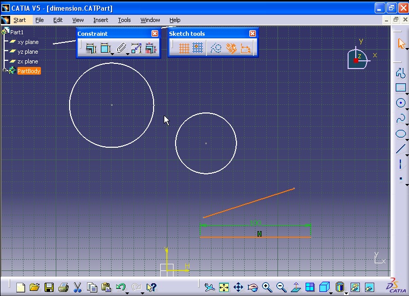
One of the measurement methods is using Constraints Defined in Dialog Box command.

To measure by using this method, First Dimensional Constraints must be active.

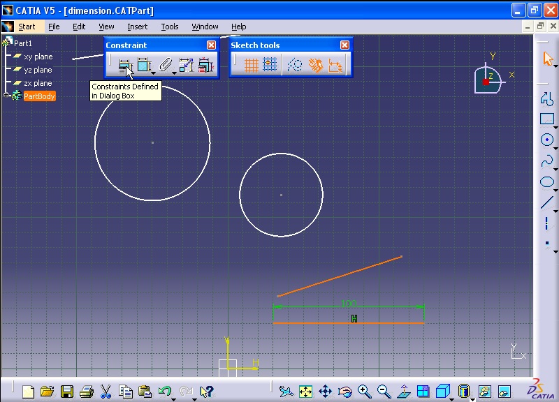
For example, first select the horizontal line and then click on Constraints Defined in Dialog Box command as shown in figure below.

Constraint Definition window opens.

From window select Length option. You will see that the dimension of the line is appeared. Then click OK to close the window.

Now double click on the dimension as shown in figure below.

Constraint Definition window opens. You can enter a new value for the Value box to change the length of the line. For example enter 100.

Then click OK to close the window and implement the change.

==========================================================
Now select the two bottom lines by holding down the Ctrl button.

Then click on Constraints Defined in Dialog Box command as shown in figure below.

Constraint Definition window opens. From window select Angle option. You will see that the angle between two lines is appeared.

Double click on the angle. Constraint Definition window opens. You can change the angle between the two lines.

For example enter value of 30 degree and click OK.

Now the dimension is changed to the new angle.

To measure the diameter of a circle, first select the circle then click on Constraints Defined in Dialog Box command as shown in figure below.

Constraint Definition window opens. From window select Radius/Diameter option. The diameter of the circle is displayed. Click OK to close the window.

By double clicking on the diameter dimension of the circle, Constraint Definition window opens.

You can change the option from diameter to radius and change the value of the radius.

Click OK to see the changes.

Now select the two circles together by holding down the Ctrl key. Then click on Constraints Defined in Dialog Box command as shown in figure below.

Constraint Definition window opens. You can enter a new value for the Value box to change the length of the line. For example enter 100.

Then click OK to close the window and implement the change.

==========================================================
Now select the two bottom lines by holding down the Ctrl button.
Then click on Constraints Defined in Dialog Box command as shown in figure below.
Constraint Definition window opens. From window select Angle option. You will see that the angle between two lines is appeared.

Double click on the angle. Constraint Definition window opens. You can change the angle between the two lines.

For example enter value of 30 degree and click OK.

Now the dimension is changed to the new angle.

To measure the diameter of a circle, first select the circle then click on Constraints Defined in Dialog Box command as shown in figure below.

Constraint Definition window opens. From window select Radius/Diameter option. The diameter of the circle is displayed. Click OK to close the window.

By double clicking on the diameter dimension of the circle, Constraint Definition window opens.

You can change the option from diameter to radius and change the value of the radius.

Click OK to see the changes.

Now select the two circles together by holding down the Ctrl key. Then click on Constraints Defined in Dialog Box command as shown in figure below.

From window select Distance option. You will see that the distance dimension appears between the two circles.

NOTE: The distance between the two circles depends on which point of circle you click and the distance measurement is different.
For example, first click on the first circle as shown in figure below.

Then click on the second circle as shown in figure below.

Then click on Constraints Defined in Dialog Box command as shown in figure below.

Constraint Definition window opens. Click on Distance option. As you see the distance dimension appears and it is different from the first distance measurement. Click OK to close the window.

==========================================================
In next stage the Constraint command from Constraint toolbar is considered. Click on the Constraint command.

And select the horizontal line.

By clicking on the screen the dimension of the line is defined in green color.

To change the dimension, double click on the dimension. Constraint Definition window opens. Then in Value box enter a new value and click OK.

To define the distance between the line and the horizontal axis, first click on Constraint command.

Then click on the line and then click on the horizontal axis as shown in figure below.

The distance between the line and the horizontal axis is defined.

If you want to change the dimension, double click on the dimension. Constraint Definition window opens. Then in Value box enter a new value and click OK.

To measure the angle between the two lines, first click on Constraint command.

Then select the two lines respectively. The angle between the two lines is defined.

If you want to change the value of the dimension. Double click on the angle. Constraint Definition window opens. Then in Value box enter a new value and click OK.

Now, click on Constraint command.

Select the inclined line.

The dimension of the inclined line is displayed.

Then right click on the dimension of the inclined line. Select Horizontal Measure Direction option.

As you can see the horizontal distance between the two end points of the inclined line is displayed.

If you want to change the distance, double click on the dimension. Constraint Definition window opens. Then in Value box enter a new value and click OK.


To measure the radius of a circle, click on Constraint command.

And click on the circle.

The radius dimension of the circle is defined.

To define the diameter of the circle, double click on the dimension. Constraint Definition window opens. Then from Dimension section select Diameter. Then in Value box enter a new value and click OK.

The new value is applied to the circle.

If you want to define the distance between a line and a circle, first click on Constraint command.

Then select the line and the circle. The distance dimension between the line and the circle appears.

Without clicking anywhere as the dimension is active, right click on the dimension and select Swap Location option.

The circle will move to the other side of the line and the distance between the line and the circle in new situation is defined.

To measure the distance between two circles, first click on the Constraint command.

Notice that the distance between the two circles depends on the points on circles on which you click and it differs.

As you can see the distance between two circles are different as clicking on different points on the circles.

To measure the distance between centers of two circles, click on Constraint command.

Select the centers of the two circles. The distance between the centres is defined.

Then without clicking anywhere right click on the dimension and select Horizontal Measure Direction option.

The horizontal distance between the centres is displayed.

If you want to see the vertical distance between the centres, again right click on the dimension and select Vertical Measure Direction option.

The vertical distance between the centres is defined.

Without clicking anywhere as the dimension is active, right click on the dimension and select Swap Location option.

The circle will move to the other side of the another circle and the distance between the centres in new situation is defined.


==========================================================
Fix Together Command:
The Fix Together command attaches selected elements together. You can select as many components as you wish, but they must belong to the active component. The components are attached to each other. Moving one of them moves the other one too.
An example is considered in order to discuss the above matter. For example a sketch is prepared which consists of three parts as shown in figure below.

The sketches are not fully constrained so they can freely move. For example the right hand sketch is clicked and moved by mouse. As you see the shape of the sketch transformed.

One method to solve this problem is using Constraint command.

But there is another method which is easy to use. And the method is Fix Together command.

Activate Fix Together command. Fix Together Definition window opens.

By drawing a window select all the members of the right hand side sketch.

The selected members are appeared in the window. Click OK to close the window.

Now if you click on one member of the sketch the rest of the sketch will move and will not transform.


Fix Together Definition window opens. By drawing a window select all the members of the sketch.


The sketch stands vertically.

Now we want to create a Coincidence constraint between the lines. First click on Constraint command.

Select the two vertical lines as shown in the figure below. The distance dimension appears between the two lines.

Without clicking anywhere, right click and select Coincidence option.

The third sketch combines with the other sketches.

If you click on the piston like shape, you will see that the piston moves down and up the cylinder.


After creating the model we can delete the Fix Together constraints. And by using Constraint command we can constraint the sketch fully and properly.

==========================================================
Auto Constraint:
It is used for dimension and constraining sketches automatically. The sketch below is not constrained.

Activate Auto Constraint. Auto Constraint window opens.

For Elements to be constrained, draw a rectangle and select all the members of the sketch.

10 lines are selected. Click OK to close the window.

The sketch is constrained automatically.

All the constraints are displayed in specification tree.

As you can see, the members of the sketch have not turned yet to green color. Because the sketch is constrained, but not constrained to the axis of coordinate system.
We have to do it manually until the sketch is fully constrained.
Click on Constraint.

Select the bottom line and the horizontal axis coordinate system.

Double click on the dimension. Constraint Definitions window opens. Change the value and click OK.

Again click on Constraint.

Select the vertical axis and the left vertical line.

Constraint Definitions window opens. Change the value and click OK.

Now the sketch is fully constrained.

Tolerances on dimensions:
First double click on a dimension.

Constraint Definition window opens. Right click on Value box and select Add tolerance... option.

Tolerance window opens. Enter 0.5mm in Maximum tolerance box and -0.3mm in Minimum tolerance box. Then click OK.

The tolerance for the dimension is created.

If you want to create tolerance for more than one dimensions, use Edit Multi-Constraint command.

Edit Multi-Constraint window opens. You can see all the dimensions existing in the sketch.

By selecting a dimension you can define the upper and lower limits of the dimension in Max Tolerance and Min Tolerance fields.

Click OK to close the window and see the results.


But there is another method which is easy to use. And the method is Fix Together command.

Activate Fix Together command. Fix Together Definition window opens.

By drawing a window select all the members of the right hand side sketch.

The selected members are appeared in the window. Click OK to close the window.

Now if you click on one member of the sketch the rest of the sketch will move and will not transform.


The Fix Together constraint is created for the other two sketches. Click on Fix Together command.

Fix Together Definition window opens. By drawing a window select all the members of the sketch.

The sketch members are appeared in the window. Click OK to close the window. The sketch is fixed.

Again, Click on Fix Together command.


The members of the sketch are appeared in the window. Click OK to close the window.

Now we can create constraints between the sketches. First we want to create the concentricity constraint between the two circles. First click on Constraint command.

Then select the two circles. The distance dimension appears between the two circles.

Without clicking anywhere, right click and select Concentricity option.

The result is that the two circles have the same centres.

By applying vertical constraint, make the line vertical. First click on Constraint command.

Click on the horizontal line. The dimension of the line appears.

Without clicking anywhere, right click and select Vertical option.

The sketch stands vertically.

Now we want to create a Coincidence constraint between the lines. First click on Constraint command.

Select the two vertical lines as shown in the figure below. The distance dimension appears between the two lines.

Without clicking anywhere, right click and select Coincidence option.

The third sketch combines with the other sketches.

If you click on the piston like shape, you will see that the piston moves down and up the cylinder.


After creating the model we can delete the Fix Together constraints. And by using Constraint command we can constraint the sketch fully and properly.

==========================================================
Auto Constraint:
It is used for dimension and constraining sketches automatically. The sketch below is not constrained.

Activate Auto Constraint. Auto Constraint window opens.

For Elements to be constrained, draw a rectangle and select all the members of the sketch.

10 lines are selected. Click OK to close the window.

The sketch is constrained automatically.

All the constraints are displayed in specification tree.

As you can see, the members of the sketch have not turned yet to green color. Because the sketch is constrained, but not constrained to the axis of coordinate system.
We have to do it manually until the sketch is fully constrained.
Click on Constraint.

Select the bottom line and the horizontal axis coordinate system.

Double click on the dimension. Constraint Definitions window opens. Change the value and click OK.

Again click on Constraint.

Select the vertical axis and the left vertical line.

Constraint Definitions window opens. Change the value and click OK.

Now the sketch is fully constrained.

Tolerances on dimensions:
First double click on a dimension.

Constraint Definition window opens. Right click on Value box and select Add tolerance... option.

Tolerance window opens. Enter 0.5mm in Maximum tolerance box and -0.3mm in Minimum tolerance box. Then click OK.

The tolerance for the dimension is created.

If you want to create tolerance for more than one dimensions, use Edit Multi-Constraint command.

Edit Multi-Constraint window opens. You can see all the dimensions existing in the sketch.

By selecting a dimension you can define the upper and lower limits of the dimension in Max Tolerance and Min Tolerance fields.

Click OK to close the window and see the results.

=========================================================
Please tell me how to activate constraint creation
ReplyDeletenice tutorials share some more tutorials keep it up
ReplyDeletehttp://www.mechanicaldesigneng.com/search/label/CATIA