How to convert a Solid Model from SolidWorks to AutoCAD
1. Create the part in SW
2. Go to 'Save As' and choose 'ACIS(*.sat)' as the 'Save as type', note the change of the dialog box
3. Locate and press the button titled 'Options...' at the left bottom corner of the 'Save As' dialog box, a new dialog box called 'Export options' will appear.
4. Make sure you have selected 'ACSI' file format, and output as 'solid/surface geometry'.
Here is the trick...
5. Under 'Version' select '1.6', the most primitive one and press 'OK'
6. Now 'Save' file
7. Run ACAD (version I am using 2008)
8. Go to 'File' and then 'Import', in the 'Import file' dialog box select 'ACIS(*.sat)' as the 'Files of type'.
9. Select the saved '.sat' file and 'Open'
10. Save the ACAD file with '.dwg' extension
It seems that ACAD doesn't support newer version of the *.sat format, therefore most people find it puzzling why it's not working as it should. Bit of logical thinking.
Changing igs part orientation/origin in SolidWorks:
There is a way in Solidworks where you can create part origin. Once you have the part in SW go to drop down menu under Insert>Reference Geometry>Coordinate System or if you have it already as I do in my tool bar. Menu opens in feature tree and asks for origin position and next three asks direction reference for XYZ . Once you create your new Coordinate System and say OK you can rename it in the feature tree.
When you save it as a file format (iges,step,parasolid,etc) under file>save as>there is an option tap-click that and the export options box comes up. At the bottom of box their is a drop down menu next to the words Output coordinate System. There you have a choice first saying default (which is the SW default) next you should see Coord System 1 or the new name you changed it to.
Convert iges 3D surface to part:
If you want surfaces, that's one thing. If you want a solid, that's another. It sounds perhaps you are NOT selecting "Try forming solid" in the Options of the File > Open dialog box, and perhaps that's really what you want to do. Even after selecting that Option, however, SolidWorks may not be successful importing to a solid body. Try with and without B-Rep mapping (with B-Rep mapping is preferable if it works, and if it doesn't it tries knitting surfaces together to form a solid). Otherwise, if you really want surfaces, not a solid or solids, try "Do not knit" if you want to be able to address individual surfaces . . . if you select "Knit surface(s)" it will probably end up as being one big surface that you can't Trim to itself or modify easily. If what you are importing is really an assembly -- more than one part -- try selecting "Import multiple bodies as parts".
How to knit surfaces in IGES file in SolidWorks:
(1)- First Create the surface model in part design

(2)- Save the model as IGES file (Select IGES format from the Save As Type box). Before saving the model as IGES, click on options in Save As window.

(3)- In the Export Options, tick IGES solid/surface entities, Export 3D Curve Features options. Then click OK and save the file.

(4)- Then open the IGES file just been created. Select IGES format from the Files of Type in box. And before clicking on Open, Click on Options.

(5)- In the Import Options select Knit surface(s) option. Then click on OK. And click Open.

(6)- The final model is one unit knitted surface.

Face Curves:
You can extract iso-parametric (UV) curves from a face or surface. Applications of this functionality include extracting the curves for imported surfaces and then performing localized cleanup using the face curves. You can specify a mesh of evenly spaced curves or a position that creates two orthogonal curves.

Mesh

Position
Each curve created by this process becomes a separate 3D sketch. However, if you are editing a 3D sketch when you invoke the Face Curves tool, all extracted curves are added to the active 3D sketch.
To extract iso-parametric curves:
(1)- Click Face Curves (Sketch toolbar) or Tools, Sketch Tools, Face Curves, then select a face or surface. Or select a face or surface, then click Face Curves or Tools, Sketch Tools, Face Curves.
A preview of the curves appears on the face. The curves are one color in one direction and another color in the other direction. The colors correspond to the colors in the Face Curves PropertyManager. The name of the face appears in the Face box.
(2)- Under Selections, choose either:
- Mesh - evenly spaced curves. Specify an integer number of curves for Direction 1 Number of Curves and Direction 2 Number of Curves
- Position - the intersection of two orthogonal curves. Drag the position in the graphics area or specify the percentage distance from the bottom for Direction 1 Number of Curves and from the right for Direction 2 Number of Curves.
Direction 1 Number of Curves or Direction 2 Number of Curves . Clear if the curve is not required. Position Vertex . Select a vertex or point to specify the intersection of the two curves.
Under Options, select or clear: Constrain to model. When selected, the curves are updated if the model changes. Ignore holes. Use for imported surfaces with internal gaps or loops. When selected, the curves are generated across holes as though the surface were intact. When cleared, the curves stop at the edges of holes. Click OK. The curves appear as 3D sketches in the FeatureManager design tree.
How to export an AutoCAD drawing as IGES (AutoCAD Mechanical 2010):
1) As the drawing file is open click on File menu then click on Export... finally click on IGES...

2) Then you will be asked to enter the file name. Here you have to enter the name with extension of igs in IGES Filename: section (e.g. yashar.igs).

3) When Options File: appear just hit enter and the IGES file will be saved in your desktop.

How to reorient and customize the view in SolidWorks:
SolidWorks Reorient Standard Views:
1. Sometimes it is beneficial to reorient your SolidWorks standard views on a part so that a typical, three-view drawing will display as required.
2. Orient your SolidWorks part to what should be the front view. (Hint: You can use Normal To views by
selecting a face to view normal to and then control-select a face that represents the vertical direction
of the new view. This will cause the Normal To view to turn appropriately).
3 Turn on the View Orientation tool by hitting the space bar or clicking on the View toolbar.
4. Select *Front from the list (don't double-click) and click Update Standard Views.
==========================================================
3DS Export for SolidWorks:
It is a 3D Studio 3DS file export add-in for SolidWorks. This add-in gives SolidWorks the ability to export 3D solid and surface data from a SolidWorks part and assembly document to meshes in a 3DS file.3DS Export for SolidWorks is an add-in for SolidWorks. The 3DS file format is the native file format of 3D Studio. 3D Studio has now been replaced by 3ds Max whose native file format has a .max file extension.
Installation:
3DS Export for SolidWorks has to be loaded into SolidWorks before it can be used. The installer adds 3DS Export for SolidWorks to the list of existing add-ins installed for SolidWorks. To load 3DS Export for SolidWorks carry out the following steps:
- Select Add-Ins from the Tools menu. The list of installed, compatible software shows in the Add-Ins dialog box
- From the list, select "3DS Export for SolidWorks" by checking its check box
- Click OK
Usage:
3DS Export for SolidWorks adds new commands to SolidWorks. It also adds a sub menu called "3DSExport" to the SolidWorks Part and Assembly menus. Simply click on the menu items in this sub menu to run these new commands. The new commands are:
- Export - Export meshes to a 3DS file
- Help - Display the 3DS Export for SolidWorks help file
- Register - Register your copy of 3DS Export for SolidWorks
- About - Display the 3DS Export for SolidWorks about box
=========================================================
How to Extract a surface or part from a multi surface or multi part environment:
For example there are three surfaces in a file and I want to extract only one of the surfaces. At first step save the file as IGES.

1. First select the surface you want to isolate and extract then right click on it and choose Isolate command.

3. After selecting Isolate the other objects will disappear.

4. Again select the isolated surface and then in File menu select Save As...

5. Resave the overwrite the file as IGES format again. Export window will appear. This box has different options (Selected face(s) - Selected bodies - All bodies). Select Selected face(s) and click OK.

6. When you open the re-saved file (IGES format) you will see that only the selected surface is saved and the other two surfaces are excluded.
=====================================================
 In the 'Parts Menu' you will need to select the entire Assembly by clicking on its title (as seen below).


=====================================================
Importing 3D model from SolidWorks to 3ds Max - Converting 3D model to Concept Sketch Model:
I have created a simple model with 3 components and I want to get it into 3ds Max. The model is in assembly format.You want to render or animate with the best you can't go wrong with 3dsMax. Before starting I want to give a few SolidWorks tips to getting it right the first time. When you are creating your model make it out of several components that come together in an assembly. This insures that each component is separate when exporting, this also makes it easier to render and to animate.
I have created a simple model with 3 components and I want to get it into 3ds Max. The model is in assembly format.You want to render or animate with the best you can't go wrong with 3dsMax. Before starting I want to give a few SolidWorks tips to getting it right the first time. When you are creating your model make it out of several components that come together in an assembly. This insures that each component is separate when exporting, this also makes it easier to render and to animate.
A rule of thumb is to build it like it would be built in reality, this is more time consuming but gives the model much more versatility. You can always simplify later. I have a simple assembly model consists of cylinder, small cube and big cube.
In the 'Parts Menu' you will need to select the entire Assembly by clicking on its title (as seen below).
Next you need to export the model by choosing 'Save As' from the File menu. You will need to select the type of file you will be exporting. This will be a Stereolith or 'STL', the type of file used in Stereolithography. Choose a file name, and set the coordinate system to 'default'. Last but not least you will need to adjust the output options by clicking on the 'Options' button. By exporting the model from the Assembly each part will maintain its position in the model, saving you time and the chance for mistakes.
In the 'Options' menu, you will need to adjust your setting to match those below. This will guarantee that your model will look its best and be very easy to work with, and hey you could even get it produced with a few grand. If you have problems with mesh quality later on you may choose to increase the 'Total quality' using the 'Custom' setting.
Once you click 'Ok', SolidWorks will think for a bit (see the progress bar at the bottom of the screen). After this process is done you will be prompted with its results (below), if this looks right you have properly exported the file and you can click 'Yes'. Congratulation!
Now you will need to start 3dsMax to begin the import of your new STL. From the File menu in 3dsMax, select 'Import', and one at a time import each of the models parts.
As you import each part you will be prompted with the below import screen. By selecting the options I have below you will maximize the quality of your model in 3dsMax insure that you computer will not lockup on you. The 'Quick Weld' is the key to making this whole process work. You will need to make sure that these options don't change as you import each part.
Your components should all be imported now and they should be in the exact location you placed them in the Assembly in SolidWorks, which makes the extra effort worth it.
You are now free to assign materials, edit, render, and animate you model. Also you will be able to mix your imported model with any type of model.
==========================================================
Converting 3D model to Concept Sketch Model:
Sketchup is a 3D CAD modeling program designed for professional architects, civil engineers, engineers, filmmakers, game developers, and related professions. It was designed to be more intuitive, flexible, and easier to use than other 3D modeling programs, which often require steep learning curves. Developed for the conceptual stages of design, this powerful software allows for quick and easy 3D form creation, the result is an interface that supports a dynamic, creative exploration of 3D form, material and light. It is a powerful software for conceptual design stage (Sketching - free hand sketch). I recommend the software especially for designers who wants to carry out the conceptual design stage. It is marketed as an easy-to-use conceptual tool with a simple interface.
Some of its key features and uses include:
- A "smart" drawing cursor (inference) system that allows users to draw 3D objects using a 2D screen and mouse
- Simple massing study capability via "push-pull"
- An interactive Heliodon, or sun angle simulator
- Ability to animate camera and sun movements
- Models can be individually colored with an assortment of solid colors, textures and materials
- Interoperability with Google Earth
- Easy to use
- Easy to learn
I will introduce a program called Google SketchUp which is free and can be downloaded from the link below: http://sketchup.google.com/
The application of the program is easy and in this tutorial I will explain how to convert a 3D CAD model to a sketch concept through application of Google SketchUp.
Step 1: A 3D model is created.
Step 2: From Menu select window and then select Styles option.
Step 3: Styles window will open.
Step 4: From Styles window I have selected a sketch pattern (You can select different patterns with various line thickness and color).
Final Sketch Design
Google SketchUp 6 is free and you can download the software from the link below:
Google SketchUp Pro 6 is not free but you can fill a form and get an 8 hours trial software.
again you can get an 8 hours trial software from link below:
===========================================================
Adobe is well known for its PDF file viewer and PDF has fast become the de facto standard for business and web-based documents. With recent releases of Adobe Acrobat and complimentary software the company have promoted themselves as offering "Adobe Design Solutions" and through their Adobe Solutions web page (http://www.adobe.com/solutions/) suggest that "no matter who you are or where you work, Adobe can make a difference" and for manufacturing Adobe suggest that users can "Streamline the design and manufacturing process and accelerate time to market".
Furthermore through their Adobe Acrobat 3D web pages (http://www.adobe.com/products/acrobat3d/) they suggest, among other benefits, that their Adobe Acrobat 3D software empowers CAD, CAM, and CAE users to convert virtually any CAD file to a highly compressed 3D PDF file to enable 3D-based collaboration and CAD data Interoperability Increase engineering productivity by sharing Adobe PDF files containing precise geometry and product manufacturing information with users of free Adobe Reader® software to mark up 3D designs, or leverage Adobe PDF files for downstream manufacturing processes without having to buy CAD translators.
==========================================================


Commercial Part:
 =========================================================


==========================================================
Making Animation in SolidWorks:
Step 1:
Step 1:
Open your assembly in SolidWorks. then right-click in configuration Manager tab. and click on New Exploded view...
Step 2:
Explode your assembly.
Step 3:
Expand Default[ Assembly]. Then Right-click ExplView1. and click on Animate collapse. The Animation Controller will appear. and all the parts will start to assemble.
Step 4:
You can save your animation as AVI by clicking on Save option in Animation Controller.
I have uploaded the video clip (AVI format) of the assembly explained above, to the next post.
====================================================
====================================================
Project Template:
The template is built for each project. Before starting any project you need to create a template.


The name of the template is the same as the name of the project.


=========================================================
Project Template Reference:


Part Configuration:


===========================================================
Save in Parts:


Save as option:


"Save as copy and open" option:


How to make a part (in subassembly) movable in the whole assembly:


Pack & Go vs Save as:
Pack & Go:


Save as:
When there are two different assemblies which have similar components.


Method 1 (Part Rename):

Method 2: Double click on the name of the part in assembly when the part is open in SolidWorks.


===========================================================
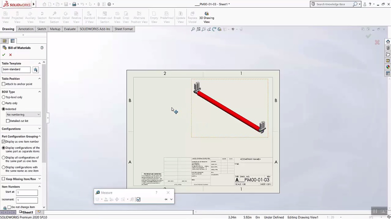
BOM (Bill of Material):


Parts only:


Top level:

Indented:


Welded parts:


How to add dimensions of a component to Description in File Properties:


Click on each dimension in the model and insert 'X' between the dimensions.


How to exclude commercial assembly parts from BOM:


Such a Nice post. Thanks for Awesome tips Keep it up
ReplyDeletesolidworks crack
dj music mixer pro crack
dvdfab Crack
emeditor professional Crack
ReplyDeleteI am happy after visited this site. It contains valuable data for the guests. Much thanks to you!
Vstmania.co
Driver Easy Professional Crack
Avira Antivirus Pro Crack
NCH DreamPlan Plus Crack
SolidWorks Crack
WebcamMax Crack
Registry First Aid Platinum Crack
CorelDRAW Graphics Suite Crack
Toontrack Superior Drummer Crack
Wilcom Embroidery Studio Crack
AntiBrowserSpy Pro Crack
Waves Tune Real Time Crack
Soothe 2 VST Crack
SoundToys Crack
UAD Ultimate 10 Bundle Crack
Slate Digital Complete Bundle Mac Crack
Adobe Acrobat Pro DC Crack
ReplyDeleteHowever, stopping by with great quality writing, it's hard to see any good blog today.
https://crackpul.com/
GstarCAD Professional Crack
FontCreator Crack
AlterCam Crack
4K Video Downloader Crack
Rekordbox DJ Crack
Macro Recorder Crack
AlterPDF Pro Crack
I am very impressed with your post because this post is very beneficial for me and provide a new knowledge…
ReplyDeletesolidworks-crack
I like your all post. You have done really good work. Thank you for the information you provide, it helped me a lot. I hope to have many more entries or so from you.
ReplyDeleteVery interesting blog.
SolidWorks Crack
Pixellu SmartAlbums Crack</a
I like your all post. You have done really good work. Thank you for the information you provide, it helped me a lot. I hope to have many more entries or so from you.
ReplyDeleteVery interesting blog.
FontCreator Pro Crack
Pixellu SmartAlbums ProCrack
if you're seeking top-notch SolidWorks Training in Noida, look no further than APTRON. Our commitment to excellence, industry-focused curriculum, experienced instructors, and state-of-the-art facilities make us the ideal choice for anyone looking to master SolidWorks.
ReplyDeleteWelcome to the forefront of engineering excellence! APTRON Solution in Noida proudly presents its SolidWorks Institute in Noida, a hub of innovation and skill development for aspiring engineers and designers. As technology continues to advance, mastering industry-standard tools like SolidWorks becomes imperative, and APTRON Solution stands as a beacon of expertise in this realm.
ReplyDeleteSolidWorks is a critical tool in the modern engineering and design landscape, and mastering it can significantly enhance your career prospects. APTRON Solution Noida offers a comprehensive, hands-on training program at SolidWorks Training Institute in Noida, guided by experienced professionals and tailored to current industry needs. With its state-of-the-art facilities, flexible learning options, and strong emphasis on practical skills, APTRON is the ideal place to start or advance your journey in mastering SolidWorks. Enroll today and take the first step towards becoming a proficient SolidWorks professional.
ReplyDeleteSolidWorks' simulation capabilities saved me time and money by allowing me to test my designs virtually before prototyping - a game-changer for ensuring product reliability.
ReplyDeletehttps://softwarefree.org/solidworks-sp4-premium/
Our SolidWorks Course in Noida at APTRON Solutions stands out for its comprehensive curriculum, expert instructors, and hands-on approach. Whether you're a beginner or looking to advance your existing skills, our course caters to all levels of proficiency. What sets APTRON Solutions apart is our commitment to providing practical, real-world training. Our experienced instructors guide you through every aspect of SolidWorks, from the basics of 3D modeling to advanced techniques such as simulation and rendering.
ReplyDelete