Element type: Solid - 8 node 82 (PLANE82). Click Options and from Element behavior select plane strain.
Besides defining element for model we need to define another two elements for surface and target element, for meshing the contact area.
Element type: Contact - 2D target 169 (TARGE169)
Element type: Contact - 3 nd surf 172 (CONTA172)

To create a physical contact between two components: Modeling - Operate - Booleans - Glue. And select two areas.

Meshing areas of contact: Meshing - Size Cntrls - ManualSize - Lines - PickedLines. Then select two lines.

The Element Sizes on picked Lines window appears. Enter 60 in No. of element divisions box. And 1/10 in Spacing ration box.
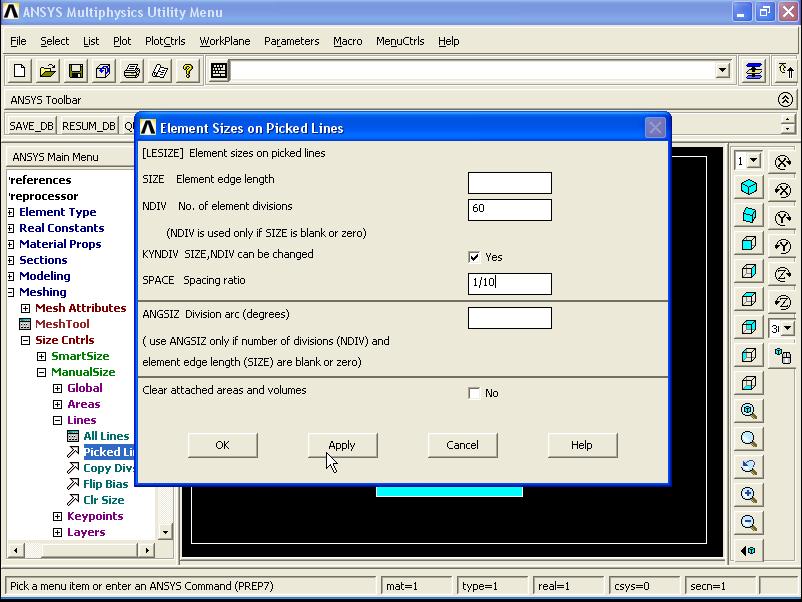
Then click Apply. And select the other two lines. Click on OK.

Element sizes on Picked Lines window appears. Enter 60 in No. of element divisions and 10 in Spacing ratio. Then click Apply.

Select the line and arc on the quarter circle.

Then click OK. Element sizes on Picked Lines window appears. Enter 40 in No. of element divisions and 10 in Spacing ratio. Then click Apply. And finally for the top line of the quarter circle enter 40 and 1/10 respectively for No. of element divisions and 10 for Spacing ratio.
After meshing the model, the target and surface elements need to be meshed.
1) All the nodes on arc section of the quarter circle must be selected (Select - Entities)

Then select the nodes close to the contact area.
1) All the nodes on arc section of the quarter circle must be selected (Select - Entities)

Then select the nodes close to the contact area.


Then, from elements - surf/contact - Surf to surf - The Mesh Free Surfaces window appears. From surface element form list select Bottom surface. Click OK.

Then select the nodes. Click OK.

Again follow the above procedure to apply the TARGE169 element to the bottom area (smooth surface).
==========================================================
==========================================================


==========================================================
==========================================================
Contact Stress (3D Analysis):
Material: Steel
Friction coefficient: 0.1
P = 0.5 MPa

Element type: Solid - Brick 8node 185 (SOLID185)
In Material Props - Material Models enter values of EX = 2.1e9, PRXY = 0.3. Click OK.
Creating the symmetrical 3D model:

Meshing the model: Meshing - Mesh Tool - click on set in front of Lines - Select two lines of wheel and click OK.

Element sizes on Picked Lines window appears. Enter value of 30 in No. of element division section. Uncheck NDIV can be changed option. Click OK.

Now meshing of rail is the same as wheel procedure.
In mesh tool window - from mesh select volumes - Select shape: Hex - Select Sweep - Click Sweep button.

Then by clicking on Pick All button, all the model are meshed.

Next, from PlotCtrls - Style - Size and Shape - the size and shape window appears. From Facets/element edge select 2 facets/edge. Then click OK. It will cause the better display of elements.

Next step, it is required to define the contact surfaces and create the contact elements. To do this, Go to modeling - Create - Contact pair - Contact manager window appears - Then click on Contact Wizard button.

The contact wizard window appears - Select Areas and Flexible and then click on Pick Target ... button.

Select Areas for Target window appears. Then in graphic area, select the top surface of rail.

Then click on Next on wizard, in next page select areas and surface-to-surface options. And click on Pick contact... button.

Then select the bottom surface of the wheel.

Then click on Next. In next page, deactivate Include initial penetration. And enter value of 0.1 in coefficient of Firiction. Then click on Optional settings button.

The contact properties window appears. In Basic tab, enter value of 0.1 in Normal penalty stiffness. Then enter Friction tab, and from stiffness matrix select Unsymmetric, then enter Initial Adjustment tab, and select close gap from Automatic contact adjustment then click on OK.

Next click on Create> button. Then click on Finish button.

Close Contact Manager window. At next step we need to define boundary conditions.
Loads - Define Loads - Apply - Structural - Displacement - On Areas - Then select the rare surfaces of the rail and wheel and click on OK.

Then select UX = 0 and click OK.
Select the other two surfaces and select UZ = 0 and click OK.

In next step, select the bottom surfaces of the rail and select UY = 0 and click OK.

Now apply the P pressure on top surface of the wheel. Structural - Pressure - On Areas - Select the top surface of the wheel and click OK. Enter value of 0.5 MPa. Click OK. Now the problem is ready to be solved.

Amazing blog thank you Structural Analysis in India
ReplyDelete