Enforced Displacement (Axisymmetric):
There are two components: One is an Aluminium plate (Bottom) which its outer edge is restrained and the other component is a Piston which press down on the bottom plate. The aim is to find:
There are two components: One is an Aluminium plate (Bottom) which its outer edge is restrained and the other component is a Piston which press down on the bottom plate. The aim is to find:
- Displacement
- Stress when the piston is pressed down on the plate and moved 0.1 inch (Displacement = 0.1 inch)

1). To define Element Types, from Main Menu click Preprocessor - Element Type - Add/Edit/Delete. Element Types window appears. Click on Add button. Library of Element Types window appears. From left column select Solid and from right column select Quad 4node 42. Click OK. PLANE42 is added to the Element Types window. From window click on Options... button. From Element Behavior list select Axisymmetric. Click OK and close Element Types window.

2). To define Material Properties, from Main Menu click Preprocessor - Material Props - Material Models. From the window click Structural - Linear - Elastic - Isotropic. For the Aluminum part Enter EX = 10e6 and PRXY = 0.35. Click OK.

To define the second Material Properties of Steel, In Define Material Model Behavior window, from menu click Material - New Model...

Define Material ID window appears. Click on OK.

Then in Define Material Model Behavior window click Structural - Linear - Elastic - Isotropic. For material number 2 enter EX = 10e6 and PRXY = 0.3 and click OK.

Two material properties are added to the list in Define Material Model Behavior window. Close the window.

3). To create the Geometry, from Main Menu click Preprocessor - Modeling - Create - Areas - Rectangle - By 2 Corners. In the window enter X = 0, Y = 0, Width = 20 inch, and Height = 0.5 inch. Click OK.


Again from Main Menu click Preprocessor - Modeling - Create - Areas - Rectangle - By 2 Corners. In the window enter X = 0, Y = 0, Width = 10 inch, and Height = 1.5 inch. Click OK.


Again from Main Menu click Preprocessor - Modeling - Create - Areas - Rectangle - By 2 Corners. In the window enter X = 0, Y = 0, Width = 1 inch, and Height = 5.5 inch. Click OK.


Then from Main Menu click Preprocessor - Modeling - Operate - Booleans - Overlap - Areas. Overlap Areas window appears. Click on Pick All window.

Then from Main Menu click PlotCtrls - Numbering...
Plot Numbering Controls window appears. Activate Area numbers and click OK.

The areas are numbered. 6 separate areas are created.

4). To Mesh the model, from Main Menu click Preprocessor - Meshing - Size Cntrls - Manual Size - Global - Size. Global Element Sizes window appears. In Element edge length box enter 0.2 inch. Click OK.

Then from Main Menu click Preprocessor - Meshing - Mesh - Areas - Mapped - 3 or 4 sided. Mesh Areas window appears. Select the bottom rectangles for the Aluminum component. Click OK.

This component is meshed with the material number 1 which is selected by default.

To mesh the Steel component, from Main Menu click Preprocessor - Meshing - Mesh Attributes - Default Attribs. Meshing Attributes window appears. Expand Material number list and select number 2. Click OK.

Then from Main Menu click Preprocessor - Meshing - Mesh - Areas - Mapped - 3 or 4 sided. Mesh Areas window appears. Pick the top rectangles for the Steel components. Click OK.


5). To apply Boundary Conditions, from Main Menu click Preprocessor - Loads - Define Loads - Apply - Structural - Displacement - On Nodes. Apply U, ROT on Nodes window appears. Select Box option from the window and pick the nodes by creating a rectangle as shown in image below. Click OK.

In the window select All DOF from list and click OK.

Repeat the above process this time select the top nodes. From Main Menu click Preprocessor - Loads - Define Loads - Apply - Structural - Displacement - On Nodes. Apply U, ROT on Nodes window appears. Select Box option from the window and pick the top nodes by creating a rectangle as shown in image below. Click OK.

Apply U, ROT on nodes window appears. From list select UY option. In Displacement value box enter -0.1 inch and click OK.

 ==========================================================
Solution Stage:
From Main Menu click Solution - Solve - Current LS. Click OK. The solution starts then close the window.

===========================================================
Post Processing Stage:
From Main Menu click Preprocessor - General Postproc - Plot Results - Contour Plot - Nodal Solu. Contour Nodal Solution Data window appears. To view the displacement along Y axis, select DOF Solution - Y-Component of displacement. Click OK.

Displacement vector sum:

X-Component of stress:

Y-Component of stress:

XY Shear Stress:

von Mises stress:
 =========================================================
=========================================================
Cylindrical Rod (Axisymmetric):

This problem was solved previously by using 1D Link element.


To define the second Material Properties of Steel, In Define Material Model Behavior window, from menu click Material - New Model...

Define Material ID window appears. Click on OK.

Then in Define Material Model Behavior window click Structural - Linear - Elastic - Isotropic. For material number 2 enter EX = 10e6 and PRXY = 0.3 and click OK.

Two material properties are added to the list in Define Material Model Behavior window. Close the window.

3). To create the Geometry, from Main Menu click Preprocessor - Modeling - Create - Areas - Rectangle - By 2 Corners. In the window enter X = 0, Y = 0, Width = 20 inch, and Height = 0.5 inch. Click OK.


Again from Main Menu click Preprocessor - Modeling - Create - Areas - Rectangle - By 2 Corners. In the window enter X = 0, Y = 0, Width = 10 inch, and Height = 1.5 inch. Click OK.


Again from Main Menu click Preprocessor - Modeling - Create - Areas - Rectangle - By 2 Corners. In the window enter X = 0, Y = 0, Width = 1 inch, and Height = 5.5 inch. Click OK.


Then from Main Menu click Preprocessor - Modeling - Operate - Booleans - Overlap - Areas. Overlap Areas window appears. Click on Pick All window.

Then from Main Menu click PlotCtrls - Numbering...
Plot Numbering Controls window appears. Activate Area numbers and click OK.

The areas are numbered. 6 separate areas are created.

4). To Mesh the model, from Main Menu click Preprocessor - Meshing - Size Cntrls - Manual Size - Global - Size. Global Element Sizes window appears. In Element edge length box enter 0.2 inch. Click OK.

Then from Main Menu click Preprocessor - Meshing - Mesh - Areas - Mapped - 3 or 4 sided. Mesh Areas window appears. Select the bottom rectangles for the Aluminum component. Click OK.

This component is meshed with the material number 1 which is selected by default.

To mesh the Steel component, from Main Menu click Preprocessor - Meshing - Mesh Attributes - Default Attribs. Meshing Attributes window appears. Expand Material number list and select number 2. Click OK.

Then from Main Menu click Preprocessor - Meshing - Mesh - Areas - Mapped - 3 or 4 sided. Mesh Areas window appears. Pick the top rectangles for the Steel components. Click OK.


5). To apply Boundary Conditions, from Main Menu click Preprocessor - Loads - Define Loads - Apply - Structural - Displacement - On Nodes. Apply U, ROT on Nodes window appears. Select Box option from the window and pick the nodes by creating a rectangle as shown in image below. Click OK.

In the window select All DOF from list and click OK.

Repeat the above process this time select the top nodes. From Main Menu click Preprocessor - Loads - Define Loads - Apply - Structural - Displacement - On Nodes. Apply U, ROT on Nodes window appears. Select Box option from the window and pick the top nodes by creating a rectangle as shown in image below. Click OK.

Apply U, ROT on nodes window appears. From list select UY option. In Displacement value box enter -0.1 inch and click OK.


Solution Stage:
From Main Menu click Solution - Solve - Current LS. Click OK. The solution starts then close the window.

===========================================================
Post Processing Stage:
From Main Menu click Preprocessor - General Postproc - Plot Results - Contour Plot - Nodal Solu. Contour Nodal Solution Data window appears. To view the displacement along Y axis, select DOF Solution - Y-Component of displacement. Click OK.

Displacement vector sum:

X-Component of stress:

Y-Component of stress:

XY Shear Stress:

von Mises stress:

=========================================================
Cylindrical Rod (Axisymmetric):
In some cases, the model is created by revolution of a profile around an axis. This is called Axisymmetric. The aim is to find:
- Displacement of the bar due to its weight

This problem was solved previously by using 1D Link element.

1). To define Element Types, from Main Menu click Preprocessor - Element Type - Add/Edit/Delete. Element Types window appears. Click on Add button. Library of Element Types window appears. From left column select Solid and from right column select Quad 4node 42. Click OK.

PLANE42 is added to the Element Types window.

From window click Options button. PLANE42 element type options window appears. From element behavior list select Axisymmetric option. Click OK. Close Element Types window.


2). To define Material Properties, click Preprocessor - Material Props - Material Models. Define Material Model Behavior window appears. From window click Structural - Linear - Elastic - Isotropic. Enter EX = 30e6 and PRXY = 0.3 and click OK.

To define the density of the bar, in the Define Material Model Behavior window click Density. Enter DENS = 0.283 and click OK.

3). To create the Geometry, from Main Menu click Preprocessor - Modeling - Create - Areas - Rectangle - By 2 Corners. Enter X = 0, Y = 0, Width = 2 inch, and Height = 20 inch and click OK.


4). To Mesh the model, from Main Menu click Preprocessor - Meshing - Mesh Tool. Mesh Tool window appears. Click on Areas Set button. Pick the area and click OK.

Element Size at Picked Areas window appears. In Element edge length box enter 0.2 inch and click OK.

In Mesh Tool window click Mesh button and then pick the area. Click OK.

The model is meshed.

5). To apply Boundary Conditions, from Main Menu click Preprocessor - Loads - Define Loads - Apply - Structural - Displacement - On Nodes. Select Box option from window. Pick all the top edge nodes by creating a rectangle. Click OK.

Apply U, ROT on Nodes window appears. Select All DOF from list and click OK.

6). To apply Gravity, from Main Menu click Preprocessor - Loads - Define Loads - Apply - Structural - Inertia - Gravity - Global. Apply (Gravitational) Acceleration window appears. In Global Cartesian Y-comp box enter -388.22 and click OK.
 ==========================================================
Solution Stage:
From Main Menu click Solution - Solve - Current LS. Click OK. Close the window.
 =========================================================
Post Processing Stage:
From Main Menu click General Postproc - Plot Results - Contour Plot - Nodal Solu. Contour Nodal Solution Data window appears. Select DOF Solution - Y-Component of displacement and click OK.


To define the density of the bar, in the Define Material Model Behavior window click Density. Enter DENS = 0.283 and click OK.

3). To create the Geometry, from Main Menu click Preprocessor - Modeling - Create - Areas - Rectangle - By 2 Corners. Enter X = 0, Y = 0, Width = 2 inch, and Height = 20 inch and click OK.


4). To Mesh the model, from Main Menu click Preprocessor - Meshing - Mesh Tool. Mesh Tool window appears. Click on Areas Set button. Pick the area and click OK.

Element Size at Picked Areas window appears. In Element edge length box enter 0.2 inch and click OK.

In Mesh Tool window click Mesh button and then pick the area. Click OK.

The model is meshed.

5). To apply Boundary Conditions, from Main Menu click Preprocessor - Loads - Define Loads - Apply - Structural - Displacement - On Nodes. Select Box option from window. Pick all the top edge nodes by creating a rectangle. Click OK.

Apply U, ROT on Nodes window appears. Select All DOF from list and click OK.

6). To apply Gravity, from Main Menu click Preprocessor - Loads - Define Loads - Apply - Structural - Inertia - Gravity - Global. Apply (Gravitational) Acceleration window appears. In Global Cartesian Y-comp box enter -388.22 and click OK.

Solution Stage:
From Main Menu click Solution - Solve - Current LS. Click OK. Close the window.

Post Processing Stage:
From Main Menu click General Postproc - Plot Results - Contour Plot - Nodal Solu. Contour Nodal Solution Data window appears. Select DOF Solution - Y-Component of displacement and click OK.


==========================================================
==========================================================
Shell Vessel Internal Pressure (Axisymmetric):

1). To define Element Type, from Main Menu click Preprocessor - Element Type - Add/Edit/Delete. Element Types window appears. Click on Add button. Library of Element Types window appears. From left column select Shell and from right column select axi-harmon 61 and click OK.

SHELL61 is added to the Element Types window. Close the window.

2). To define Element Properties, from Main Menu click Preprocessor - Real Constants - Add/Edit/Delete. Real Constants window appears. Click on Add button. Then click on OK.

Real Constant Set Number 1, for SHELL61 window appears. In Shell thickness at node I box enter 0.25 inch. Click OK and close Real Constants window.

3). To define Material Properties, from Main Menu click Preprocessor - Material Props - Material Models. Define Material Model Behavior window appears. Click Structural - Linear - Elastic - Isotropic. Enter EX = 10e6 and PRXY = 0.3 and click OK.

4). To create the Geometry, from Main Menu click Preprocessor - Modeling - Create - Keypoints - In Active CS. Create the following points: 1.(25,0,0) - 2.(25,10,0) - 3.(15,27.32,0) - 4.(15,37.32,0) - 5.(0,52.32,0) - 6.(0,37.32,0) and click OK.


Next we need to connect the points together. From Main Menu click Preprocessor - Modeling - Create - Lines - Lines - Straight Line. Create Straight Line window appears. Connect point 1 to 2, 2-3, 3-4, and click OK.

To create the arc bit, from Main Menu click Preprocessor - Modeling - Create - Lines - Arcs - By End KPs & Rad. Arc by End KPs & Rad window appears. Pick the start and end points as shown in figure and click OK.

Then click on point 6 as the center of the arc and click OK.

Arc by End KPs & Radius window appears. In Radius of the arc box enter 15 and click OK.


Next we need to combine all the lines. From Main Menu click Preprocessor - Modeling - Operate - Booleans - Glue - Lines. Glue Lines window appears. Click on Pick All button.

5). To Mesh the model, from Main Menu click Preprocessor - Meshing - Size Cntrls - ManualSize - Lines - All Lines. Element Sizes on All Selected Lines window appears. In No. of element divisions box enter 20 and click OK.

From Main Menu click Preprocessor - Meshing - Mesh - Lines. Mesh Lines window appears. Click on Pick All button.


6). To apply Boundary Conditions, from Main Menu click Preprocessor - Loads - Define Loads - Apply - Structural - Displacement - On Nodes. Apply U, ROT on Nodes window appears. Pick the bottom end node and click OK.

Apply U, ROT on Nodes window appears. From list UY and click OK.

From Main Menu click Preprocessor - Loads - Define Loads - Apply - Structural - Displacement - On Nodes. Apply U, ROT on Nodes window appears. Pick the top end node and click OK.

Apply U, ROT on Nodes window appears. From list UX and click OK.

7). To apply internal pressure, from Main Menu click Preprocessor - Loads - Define Loads - Apply - Structural - Pressure - On Elements. Apply PRES on Elems window appears. Click on Pick All button.

Apply PRES on elems window appears. In Load PRES value box enter 300psi and click OK.

===========================================================
Solution Stage:
From Main Menu click Solution - Solve - Current LS. Click OK to start solution. Close the window.

===========================================================
Post Processing Stage:
From Main Menu click General Postproc - Element Table - Define Table. Element Table Data window appears. Click on Add button.

Define Additional Element Table Items window appears. From left column select By sequence num and from right column select LS, option. In the bottom box enter LS, 5 and click OK.

Again from Main Menu click General Postproc - Element Table - Define Table. Element Table Data window appears. Click on Add button. From left column select By sequence num and from right column select LS, option. In the bottom box enter LS, 7 and click OK.

Close Element Table Data window.

From Main Menu click General Postproc - Element Table - List Elem Table. List Element Table Data window appears. Select LS5 and LS7 and click OK.

The radial and longitudinal stresses result are displayed in the table.


==========================================================
Shell Vessel Internal Pressure (Axisymmetric):
The shell is axisymmetric around Y axis and a 300 psi internal pressure is applied. The thickness of the shell is 0.25 inch. The aim is to find displacement and stresses.

1). To define Element Type, from Main Menu click Preprocessor - Element Type - Add/Edit/Delete. Element Types window appears. Click on Add button. Library of Element Types window appears. From left column select Shell and from right column select axi-harmon 61 and click OK.

SHELL61 is added to the Element Types window. Close the window.

2). To define Element Properties, from Main Menu click Preprocessor - Real Constants - Add/Edit/Delete. Real Constants window appears. Click on Add button. Then click on OK.

Real Constant Set Number 1, for SHELL61 window appears. In Shell thickness at node I box enter 0.25 inch. Click OK and close Real Constants window.

3). To define Material Properties, from Main Menu click Preprocessor - Material Props - Material Models. Define Material Model Behavior window appears. Click Structural - Linear - Elastic - Isotropic. Enter EX = 10e6 and PRXY = 0.3 and click OK.

4). To create the Geometry, from Main Menu click Preprocessor - Modeling - Create - Keypoints - In Active CS. Create the following points: 1.(25,0,0) - 2.(25,10,0) - 3.(15,27.32,0) - 4.(15,37.32,0) - 5.(0,52.32,0) - 6.(0,37.32,0) and click OK.


Next we need to connect the points together. From Main Menu click Preprocessor - Modeling - Create - Lines - Lines - Straight Line. Create Straight Line window appears. Connect point 1 to 2, 2-3, 3-4, and click OK.

To create the arc bit, from Main Menu click Preprocessor - Modeling - Create - Lines - Arcs - By End KPs & Rad. Arc by End KPs & Rad window appears. Pick the start and end points as shown in figure and click OK.

Then click on point 6 as the center of the arc and click OK.

Arc by End KPs & Radius window appears. In Radius of the arc box enter 15 and click OK.


Next we need to combine all the lines. From Main Menu click Preprocessor - Modeling - Operate - Booleans - Glue - Lines. Glue Lines window appears. Click on Pick All button.

5). To Mesh the model, from Main Menu click Preprocessor - Meshing - Size Cntrls - ManualSize - Lines - All Lines. Element Sizes on All Selected Lines window appears. In No. of element divisions box enter 20 and click OK.

From Main Menu click Preprocessor - Meshing - Mesh - Lines. Mesh Lines window appears. Click on Pick All button.


6). To apply Boundary Conditions, from Main Menu click Preprocessor - Loads - Define Loads - Apply - Structural - Displacement - On Nodes. Apply U, ROT on Nodes window appears. Pick the bottom end node and click OK.

Apply U, ROT on Nodes window appears. From list UY and click OK.

From Main Menu click Preprocessor - Loads - Define Loads - Apply - Structural - Displacement - On Nodes. Apply U, ROT on Nodes window appears. Pick the top end node and click OK.

Apply U, ROT on Nodes window appears. From list UX and click OK.

7). To apply internal pressure, from Main Menu click Preprocessor - Loads - Define Loads - Apply - Structural - Pressure - On Elements. Apply PRES on Elems window appears. Click on Pick All button.

Apply PRES on elems window appears. In Load PRES value box enter 300psi and click OK.

===========================================================
Solution Stage:
From Main Menu click Solution - Solve - Current LS. Click OK to start solution. Close the window.

===========================================================
Post Processing Stage:
From Main Menu click General Postproc - Element Table - Define Table. Element Table Data window appears. Click on Add button.

Define Additional Element Table Items window appears. From left column select By sequence num and from right column select LS, option. In the bottom box enter LS, 5 and click OK.

Again from Main Menu click General Postproc - Element Table - Define Table. Element Table Data window appears. Click on Add button. From left column select By sequence num and from right column select LS, option. In the bottom box enter LS, 7 and click OK.

Close Element Table Data window.

From Main Menu click General Postproc - Element Table - List Elem Table. List Element Table Data window appears. Select LS5 and LS7 and click OK.

The radial and longitudinal stresses result are displayed in the table.

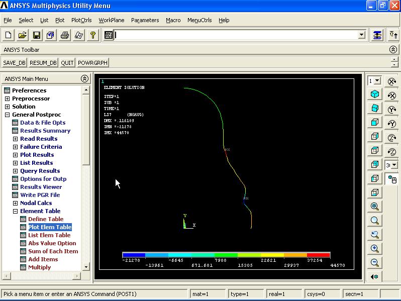
From Main Menu click General Postproc - Element Table - Plot Elem Table. Contour Plot of Element Table Data window appears. Make sure that the LS5 is selected. Click OK.


From Menu click PlotCtrls - Style - Displacement Scaling...

Displacement Display Scaling window appears. In User specified factor box enter 12.53 and click OK.

From Main Menu click General Postproc - Element Table - Plot Elem Table. Contour Plot of Element Table Data window appears. Select LS7 and click OK.

To view the displacement, from Main Menu click General Postproc - Plot Results - Deformed Shape. Plot Deformed Shape window appears. Select Def + undeformed option and click OK.


From Menu click PlotCtrls - Style - Displacement Scaling... Displacement Display Scaling window appears. From the list select 1.0 (true scale) option and click OK.


==========================================================
No comments:
Post a Comment