C-Channel Shell Analysis:
Dimensions of the channel cross section is (6 x 2 inch) and the thickness of the channel is 0.2inch. A force of 1 pound is applied equally to the end four vertices (1/4 of pound at each point) of the channel.
Dimensions of the channel cross section is (6 x 2 inch) and the thickness of the channel is 0.2inch. A force of 1 pound is applied equally to the end four vertices (1/4 of pound at each point) of the channel.

1). To define Element Type, from Main Menu click Preprocessor - Element Type - Add/Edit/Delete. Element Types window appears. Click on Add button. Library of Element Types window appears. From left column select Shell and from right column select Elastic 4node 63 and click OK. SHELL63 is added to the Element Type window.

SHELL63 is added to the Element Type window. Close this window.

2). To define Element Properties, from Main Menu click Preprocessor - Real Constants - Add/Edit/Delete. Real Constants window appears. Click on Add button. Then click on OK.

Real Constant Set Number 1, for SHELL 63 window appears. In Shell thickness at node I box enter 0.2 and click OK. The close Real Constants window.

3). To define Material Properties, from Main Menu click Preprocessor - Material Props - Material Models. Define Material Model Behavior window appears. Click Structural - Linear - Elastic - Isotropic. Enter EX = 3e7 and PRXY = 0.27 and click OK.

4). To create the Geometry, from Main Menu click Preprocessor - Modeling - Create - Keypoints - In Active CS. Creates the following points: 1.(0,-3,0) - 2.(0,3,0) - 3.(0,-3,2) - 4.(0,3,2) - 5.(30,-3,0) - 6.(30,3,0) - 7.(30,-3,2) - 8.(30,3,2) and click OK.


Then we need to connect the points together. From Main Menu click Preprocessor - Modeling - Create - Lines - Lines - Straight Line. Create Straight Line window appears. Connect point 4 to 2, 2-1, 1-3, 8-6, 6-5, 5-7, 6-2, 1-5, 8-4, 3-7 and click OK.

In next stage we need to create the areas which go through the lines. From Main Menu click Preprocessor - Modeling - Create - Areas - Arbitrary - By Lines. Create Area by Lines window appears. Pick the four lines as shown in the figure. Click OK.


From Main Menu click Preprocessor - Modeling - Create - Areas - Arbitrary - By Lines. Create Area by Lines window appears. Pick the four lines as shown in the figure. Click OK.


From Main Menu click Preprocessor - Modeling - Create - Areas - Arbitrary - By Lines. Create Area by Lines window appears. Pick the four lines as shown in the figure. Click OK.


To add these three areas, from Main Menu click Preprocessor - Modeling - Operate - Booleans - Glue - Areas. Glue Areas window appears. Click on Pick All button.


5). To Mesh the model, from Main Menu click Preprocessor - Meshing - Size Cntrls - ManualSize - Areas - All Areas. Element Sizes on All Selected Areas window appears. In Element edge length box enter 0.4 and click OK.

From Main Menu click Preprocessor - Meshing - Mesh - Areas - Mapped - 3 or 4 sided. Click Pick All button.


6). To apply Boundary Conditions, from Main Menu click Preprocessor - Loads - Define Loads - Apply - Structural - Displacement - On Lines. Apply U, ROT on Lines window appears. Pick the end three lines as shown in figure and click OK.

Apply U, Rot on Lines window appears. Select All DOF option and click OK.

7). To apply Load, from Main Menu click Preprocessor - Loads - Define Loads - Apply - Structural - Force/Moment - On Keypoints. Apply F/M on KPs window appears. Pick the four vertices of the other end as shown in figure and click OK.

Apply F/M on KPs window appears. From the list select FY. In Force/moment value box enter -1/4 and click OK.
 =========================================================
Solution Stage:
From Main Menu click Solution - Solve - Current LS. Click OK.

Close the window.
 =========================================================
Post Processing Stage:
From Main Menu click General Postproc - Plot Results - Contour Plot - Nodal Solution. Contour Nodal Solution Data window appears. Click DOF Solution - X-Component of displacement. Click OK.


Y-Component of displacement:

Z-Component of displacement:

Displacement vector sum:

Stress - X-Component of stress:

Y-Component of stress:

Z-Component of stress:

XY Shear stress:

Von Mises stress:

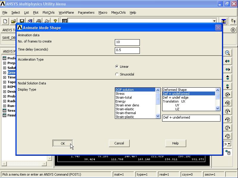
To animate the displacement, from Menu click PlotCtrls - Animate - Mode Shape. Animate Mode Shape window appears. From left column select DOF Solution and from right column select Def + undeformed. Click OK.

 ==========================================================
==========================================================
Shell/Plate Analysis:

The symmetry edges are restrained with the help of the following table:


Real Constant Set Number 1, for SHELL 63 window appears. In Shell thickness at node I box enter 0.2 and click OK. The close Real Constants window.

3). To define Material Properties, from Main Menu click Preprocessor - Material Props - Material Models. Define Material Model Behavior window appears. Click Structural - Linear - Elastic - Isotropic. Enter EX = 3e7 and PRXY = 0.27 and click OK.

4). To create the Geometry, from Main Menu click Preprocessor - Modeling - Create - Keypoints - In Active CS. Creates the following points: 1.(0,-3,0) - 2.(0,3,0) - 3.(0,-3,2) - 4.(0,3,2) - 5.(30,-3,0) - 6.(30,3,0) - 7.(30,-3,2) - 8.(30,3,2) and click OK.


Then we need to connect the points together. From Main Menu click Preprocessor - Modeling - Create - Lines - Lines - Straight Line. Create Straight Line window appears. Connect point 4 to 2, 2-1, 1-3, 8-6, 6-5, 5-7, 6-2, 1-5, 8-4, 3-7 and click OK.

In next stage we need to create the areas which go through the lines. From Main Menu click Preprocessor - Modeling - Create - Areas - Arbitrary - By Lines. Create Area by Lines window appears. Pick the four lines as shown in the figure. Click OK.


From Main Menu click Preprocessor - Modeling - Create - Areas - Arbitrary - By Lines. Create Area by Lines window appears. Pick the four lines as shown in the figure. Click OK.


From Main Menu click Preprocessor - Modeling - Create - Areas - Arbitrary - By Lines. Create Area by Lines window appears. Pick the four lines as shown in the figure. Click OK.


To add these three areas, from Main Menu click Preprocessor - Modeling - Operate - Booleans - Glue - Areas. Glue Areas window appears. Click on Pick All button.


5). To Mesh the model, from Main Menu click Preprocessor - Meshing - Size Cntrls - ManualSize - Areas - All Areas. Element Sizes on All Selected Areas window appears. In Element edge length box enter 0.4 and click OK.

From Main Menu click Preprocessor - Meshing - Mesh - Areas - Mapped - 3 or 4 sided. Click Pick All button.


6). To apply Boundary Conditions, from Main Menu click Preprocessor - Loads - Define Loads - Apply - Structural - Displacement - On Lines. Apply U, ROT on Lines window appears. Pick the end three lines as shown in figure and click OK.

Apply U, Rot on Lines window appears. Select All DOF option and click OK.

7). To apply Load, from Main Menu click Preprocessor - Loads - Define Loads - Apply - Structural - Force/Moment - On Keypoints. Apply F/M on KPs window appears. Pick the four vertices of the other end as shown in figure and click OK.

Apply F/M on KPs window appears. From the list select FY. In Force/moment value box enter -1/4 and click OK.

Solution Stage:
From Main Menu click Solution - Solve - Current LS. Click OK.

Close the window.

Post Processing Stage:
From Main Menu click General Postproc - Plot Results - Contour Plot - Nodal Solution. Contour Nodal Solution Data window appears. Click DOF Solution - X-Component of displacement. Click OK.


Y-Component of displacement:

Z-Component of displacement:

Displacement vector sum:

Stress - X-Component of stress:

Y-Component of stress:

Z-Component of stress:

XY Shear stress:

Von Mises stress:

To animate the displacement, from Menu click PlotCtrls - Animate - Mode Shape. Animate Mode Shape window appears. From left column select DOF Solution and from right column select Def + undeformed. Click OK.


==========================================================
Shell/Plate Analysis:
The thickness of the component is hugely less than other dimensions of the component. The different between plane stress and shell/plate is that in plane stress the loading is applied on the plane but in shell/plate analysis loading and moments are applied in different directions on the component not only on the plane. Thickness of the plate is 0.1 inch. And a 1 pound concentrated force is applied to the center of the plate. The aim is to find stress and displacement.

The symmetry edges are restrained with the help of the following table:

1). To define the Element Type, from Main Menu click Preprocessor - Element Type - Add/Edit/Delete. Element Types window appears. Click on Add button. Library of Element Types window appears. From left column select Shell and from right column select Elastic 4node 63. Click OK.

SHELL63 is added to the Element Types window. Close the window.

2). To define Element Properties, from Main Menu click Preprocessor - Real Constants - Add/Edit/Delete. Real Constants window appears. Click on Add button. Click OK.

Real Constant Set Number 1, for SHELL63 window appears. In Shell thickness at node I box enter 0.1 inch and click OK. Then close Real Constants window.

3). To define Material Properties, from Main Menu click Preprocessor - Material Props - Material Models. Define Material Model Behavior window appears. Select Structural - Linear - Elastic - Isotropic. Enter EX = 2.8e7 and PRXY = 0.3 and click OK.

4). As the model is symmetrical about two axis, only quarter of the model is created. To create the Geometry, from Main Menu click Preprocessor - Modeling - Create - Areas - Rectangle - By Dimensions. Create Rectangle by Dimensions window appears. Enter X1 = 0, X2 = 5, Y1 = 0, and Y2 = 5 and click OK.


5). To Mesh the model, from Main Menu click Preprocessor - Meshing - Size Cntrls - ManualSize - Lines - All Lines. In No. of element division box enter 24 and click OK.

Then from Main Menu click Preprocessor - Meshing - Mesh - Areas - Mapped - 3 or 4 sided. Mesh Areas window appears. Pick the model and click OK.


6). Before applying Boundary Conditions, the line numbers need to be displayed. From Menu click PlotCtrls - Numbering. Plot Numbering Controls window appears. Activate Line numbers. Click OK.

From Menu click Plot - Lines.

From Main Menu click Preprocessor - Loads - Define Loads - Apply - Structural - Displacement - On Lines. Apply U, ROT on Nodes window appears. Pick Line 2 and Line 3 and click OK.

From the list select UZ and click OK.

From Main Menu click Preprocessor - Loads - Define Loads - Apply - Structural - Displacement - On Lines. Apply U, ROT on Nodes window appears. Pick Line 1 and click OK.

Apply U, ROT on Lines window appears. Select UY and click OK.

From Main Menu click Preprocessor - Loads - Define Loads - Apply - Structural - Displacement - On Lines. Apply U, ROT on Nodes window appears. Pick Line 4 and click OK.

Apply U, ROT on Lines window appears. Select UX and click OK.

From Main Menu click Preprocessor - Loads - Define Loads - Apply - Structural - Displacement - On Lines. Apply U, ROT on Nodes window appears. Pick Line 1 and Line 2 and click OK.

Apply U, ROT on Lines window appears. Select ROTX and click OK.

From Main Menu click Preprocessor - Loads - Define Loads - Apply - Structural - Displacement - On Lines. Apply U, ROT on Nodes window appears. Pick Line 3 and Line 4 and click OK.

Apply U, ROT on Lines window appears. Select ROTY and click OK.

7). As the quarter of the geometry is modelled, quarter of the load is considered. To apply Load, from Main Menu click Preprocessor - Loads - Define Loads - Apply - Structural - Force/Moment - On Nodes. Apply F/M on Nodes window appears. Pick the node at the center of the coordinate system and click OK.

Apply F/M on Nodes window appears. From list select FZ and in Force/moment value box enter -1/4 and click OK.

 =============================================================
Solution Stage:
From Main Menu click Solution - Solve - Current LS. Click on OK to start solution. Close the window.
 =============================================================
Post Processing Stage:
From Main Menu click General Postproc - Plot Results - Contour Plot - Nodal Solu. Contour Nodal Solution Data window appears. Click DOF Solution - X-Component of displacement. Click OK.


Y-Component of displacement:

Z-Component of displacement:

Stress - X-Component of stress:

Y-Component of stress:

Z-Component of stress:

XY-Shear stress:

Von Mises Stress:

To view the animation, from Menu click Plotctrls - Animate - Mode Shape.

Animate Mode Shape window appears. From left column select DOF Solution and from right column select Def + undeformed. Click OK.


SHELL63 is added to the Element Types window. Close the window.

2). To define Element Properties, from Main Menu click Preprocessor - Real Constants - Add/Edit/Delete. Real Constants window appears. Click on Add button. Click OK.

Real Constant Set Number 1, for SHELL63 window appears. In Shell thickness at node I box enter 0.1 inch and click OK. Then close Real Constants window.

3). To define Material Properties, from Main Menu click Preprocessor - Material Props - Material Models. Define Material Model Behavior window appears. Select Structural - Linear - Elastic - Isotropic. Enter EX = 2.8e7 and PRXY = 0.3 and click OK.

4). As the model is symmetrical about two axis, only quarter of the model is created. To create the Geometry, from Main Menu click Preprocessor - Modeling - Create - Areas - Rectangle - By Dimensions. Create Rectangle by Dimensions window appears. Enter X1 = 0, X2 = 5, Y1 = 0, and Y2 = 5 and click OK.


5). To Mesh the model, from Main Menu click Preprocessor - Meshing - Size Cntrls - ManualSize - Lines - All Lines. In No. of element division box enter 24 and click OK.

Then from Main Menu click Preprocessor - Meshing - Mesh - Areas - Mapped - 3 or 4 sided. Mesh Areas window appears. Pick the model and click OK.


6). Before applying Boundary Conditions, the line numbers need to be displayed. From Menu click PlotCtrls - Numbering. Plot Numbering Controls window appears. Activate Line numbers. Click OK.

From Menu click Plot - Lines.

From Main Menu click Preprocessor - Loads - Define Loads - Apply - Structural - Displacement - On Lines. Apply U, ROT on Nodes window appears. Pick Line 2 and Line 3 and click OK.

From the list select UZ and click OK.

From Main Menu click Preprocessor - Loads - Define Loads - Apply - Structural - Displacement - On Lines. Apply U, ROT on Nodes window appears. Pick Line 1 and click OK.

Apply U, ROT on Lines window appears. Select UY and click OK.

From Main Menu click Preprocessor - Loads - Define Loads - Apply - Structural - Displacement - On Lines. Apply U, ROT on Nodes window appears. Pick Line 4 and click OK.

Apply U, ROT on Lines window appears. Select UX and click OK.

From Main Menu click Preprocessor - Loads - Define Loads - Apply - Structural - Displacement - On Lines. Apply U, ROT on Nodes window appears. Pick Line 1 and Line 2 and click OK.

Apply U, ROT on Lines window appears. Select ROTX and click OK.

From Main Menu click Preprocessor - Loads - Define Loads - Apply - Structural - Displacement - On Lines. Apply U, ROT on Nodes window appears. Pick Line 3 and Line 4 and click OK.

Apply U, ROT on Lines window appears. Select ROTY and click OK.

7). As the quarter of the geometry is modelled, quarter of the load is considered. To apply Load, from Main Menu click Preprocessor - Loads - Define Loads - Apply - Structural - Force/Moment - On Nodes. Apply F/M on Nodes window appears. Pick the node at the center of the coordinate system and click OK.

Apply F/M on Nodes window appears. From list select FZ and in Force/moment value box enter -1/4 and click OK.


Solution Stage:
From Main Menu click Solution - Solve - Current LS. Click on OK to start solution. Close the window.

Post Processing Stage:
From Main Menu click General Postproc - Plot Results - Contour Plot - Nodal Solu. Contour Nodal Solution Data window appears. Click DOF Solution - X-Component of displacement. Click OK.


Y-Component of displacement:

Z-Component of displacement:

Stress - X-Component of stress:

Y-Component of stress:

Z-Component of stress:

XY-Shear stress:

Von Mises Stress:

To view the animation, from Menu click Plotctrls - Animate - Mode Shape.

Animate Mode Shape window appears. From left column select DOF Solution and from right column select Def + undeformed. Click OK.

==========================================================
==========================================================
Shell/Plate analysis in ANSYS:


Shell/Plate analysis in ANSYS:
The thickness of the component is hugely less than other dimensions of the component. The different between plane stress and shell/plate is that in plane stress the loading is applied on the plane but in shell/plate analysis loading and moments are applied in different directions on the component not only on the plane.

Element type: Shell - Elastic 4node 63 (SHELL63).


Element type: Shell - Axi-harmon 61 (SHELL61): This element is used for axisymmetric shell problems.

Model of vessel in ANSYS:

==========================================================
==========================================================
Symmetrical Shell Bracket:


Set 1 is added to the Real Constants list. Close this window.

3). To define Material Properties, from Main Menu click Preprocessor - Material Props - Material Models. Define Material Model Behavior window appears. Click Structural - Linear - Elastic - Isotropic. Enter EX = 3e7 and PRXY = 0.3 and click OK.

4). Before creating the Geometry we need to change the coordinate system. From Menu click WorkPlane - Offset WP by Increments. Offset WP window appears. In X,Y,Z Offsets box enter 0,3,-2 and click OK.


From Main Menu click Preprocessor - Modeling - Create - Areas - Rectangle - By Dimensions. Create Rectangle by Dimensions window appears. Enter X1 = -2 , X2 = 0, Y1 = 0, and Y2 = 2 and click OK.


From Main Menu click Preprocessor - Modeling - Create - Areas - Circle - By Dimensions. Circular Area by Dimensions window appears. Enter Outer radius = 1, Optional inner radius = 0, Starting angle (degrees) = 90, and Ending angle (degrees) = 180 and click OK.


The bracket is made up of Steel and its thickness is 0.1 inch.

1). To define the Element Type, from Main Menu click Preprocessor - Element Type - Add/Edit/Delete. Element Types window appears. Click on Add button. Library of Element Types window appears. From left column select Shell and from right column select Elastic 4node 63 and click OK.

SHELL63 is added to the Element Types window. Close the window.

2). To define Element Properties, from Main Menu click Preprocessor - Real Constants - Add/Edit/Delete. Real Constants window appears. Click on Add button. Then click OK. Real Constant Set Number 1, for SHELL63 window appears. In Shell thickness at node I box enter 0.1 and click OK.

Set 1 is added to the Real Constants list. Close this window.

3). To define Material Properties, from Main Menu click Preprocessor - Material Props - Material Models. Define Material Model Behavior window appears. Click Structural - Linear - Elastic - Isotropic. Enter EX = 3e7 and PRXY = 0.3 and click OK.

4). Before creating the Geometry we need to change the coordinate system. From Menu click WorkPlane - Offset WP by Increments. Offset WP window appears. In X,Y,Z Offsets box enter 0,3,-2 and click OK.

From Main Menu click Preprocessor - Modeling - Create - Areas - Rectangle - By Dimensions. Create Rectangle by Dimensions window appears. Enter X1 = -2 , X2 = 0, Y1 = 0, and Y2 = 2 and click OK.


From Main Menu click Preprocessor - Modeling - Create - Areas - Circle - By Dimensions. Circular Area by Dimensions window appears. Enter Outer radius = 1, Optional inner radius = 0, Starting angle (degrees) = 90, and Ending angle (degrees) = 180 and click OK.


Next we need to remove the circle from the rectangle. From Main Menu click Preprocessor - Modeling - Operate - Booleans - Subtract - Areas. Subtract Areas window appears. Pick the rectangle and click OK.

Then pick the circle and click OK.


Then we need to move the coordinate system to the centre of the top left hole. From Menu click WorkPlane - Offset WP by Increments. Offset WP window appears. In X,Y,Z Offsets box enter -1.5,1.5,0 and click OK.


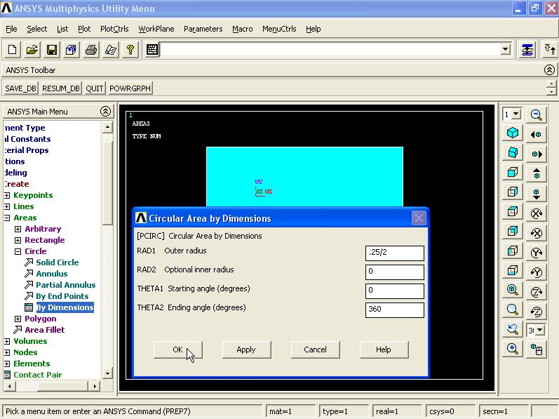
From Main Menu click Preprocessor - Modeling - Create - Areas - Circle - By Dimensions. Circular Area by Dimensions window appears. Enter Outer radius = 0.25/2, Optional inner radius = 0, Starting angle (degrees) = 0, and Ending angle (degrees) = 360 and click OK.

Next we need to remove the circle from the main area. From Main Menu click Preprocessor - Modeling - Operate - Booleans - Subtract - Areas. Subtract Areas window appears. Pick the main area and click OK.

Now pick the circle and click OK.


To create the rest of the model we need to change the coordinate system. From Menu click WorkPlane - Offset WP by Increments. Offset WP window appears. In X,Y,Z Offsets box enter -0.5,0.5,0 and click OK.


From Main Menu click Preprocessor - Modeling - Create - Areas - Rectangle - By Dimensions. Create Rectangle by Dimensions window appears. Enter X1 = 0, X2 = 1, Y1 = -2, and Y2 = -5 and click OK.


To create the curve end, from Main Menu click Preprocessor - Modeling - Create - Keypoints - In Active CS. Create the following points: 51.(0,0,0), 52.(-0.5,0,0) and click OK.


To create the end curve, from Main Menu click Preprocessor - Modeling - Operate - Extrude - Lines - About Axis. Sweep Lines about Axis window appears. Pick the line as shown in the figure and click OK.

Next define the sweep axis. In the box enter the point numbers as 51 and 52 and click OK.

Sweep Lines about Axis window appears. In Arc length in degrees box enter 45 and click OK.


In next stage we need to combine all the areas. From Main Menu click Preprocessor - Modeling - Operate - Booleans - Glue - Areas. Glue Areas window appears. Click on Pick All button.

5). To Mesh the model, from Main Menu click Preprocessor - Meshing - Size Cntrls - ManualSize - Areas - All Areas. Element Sizes on All Selected Areas window appears. In Element edge length box enter 0.2 inch and click OK.

Then from Main Menu click Preprocessor - Meshing - Mesh - Areas - Free. Mesh Areas window appears. Click on Pick All button.

As you can see, the element sizes around the hole is too big. So we need to refine the element sizes.

From Main Menu click Preprocessor - Meshing - Modify Mesh - Refine At - Lines. Refine mesh at lines window appears. Pick the lines of hole and click OK.

Refine Mesh at Line window appears. From Level of refinement select 1 (Minimal) option and click OK.


Now we want to mirror the geometry and the mesh about Y-Z plane. From Main Menu click Preprocessor - Modeling - Reflect - Areas. Reflect Areas window appears. Pick the model and click OK.

Reflect Areas window appears. Select Y-Z plane option. Click OK.

Reflecting the geometry causes nodes, keypoints and rest of the model to overlap. In this situation we will encounter problems when applying boundary conditions and loading. To solve this problem, from Main Menu click Preprocessor - Numbering Ctrls - Merge Items. Merge Coincident of Equivalently Defined Items window appears. From the top list select All and click OK.

To create the rest of the model, from Menu click WorkPlane - Local Coordinate System - Create Local CS - At Specified Loc +.

Create CS at Location window appears. In the box enter 0,0,0 and click OK.

Create Local CS at Specified Location window appears. In Rotation about local X box enter -45 degree and click OK.


Now we want to mirror the whole geometry and the mesh about X-Z plane of new local coordinate system. From Main Menu click Preprocessor - Modeling - Reflect - Areas. Reflect Areas window appears. Click Pick All button.

Reflect Areas window appears. Select X-Z Plane option. Click OK.


From Main Menu click Preprocessor - Numbering Ctrls - Merge Items. Merge Coincident of Equivalently Defined Items window appears. From the top list select All and click OK.

From Menu click Plot - Elements.

6). To apply Boundary Conditions, from Main Menu click Preprocessor - Loads - Define Loads - Apply - Structural - Displacement - On Lines. Apply U, ROT on Lines window appears. Pick the both holes edges and click OK.

From the list select All DOF and click OK.

7). To apply Loading, from Main Menu click Preprocessor - Loads - Define Loads - Apply - Structural - Force/Moment - On Nodes. Apply F/M on Nodes window appears. Now pick the nodes at hole area as shown in figure. There are 12 nodes. Click OK.

Apply F/M on Nodes window appears. From the list select FY option. In Force/moment value box enter the load which must be divided into 12 (number of nodes). Therefore, the force value equals 6/12. Click OK.

Repeat the above process to the other hole. From Main Menu click Preprocessor - Loads - Define Loads - Apply - Structural - Force/Moment - On Nodes. Apply F/M on Nodes window appears. Now pick the nodes at hole area as shown in figure. There are 12 nodes. Click OK.

Apply F/M on Nodes window appears. From the list select FY option. In Force/moment value box enter the load which must be divided into 12 (number of nodes). Therefore, the force value equals 6/12. Click OK.

=========================================================
Solution Stage:
From Main Menu click Solution - Solve - Current LS. Click OK to start solution. Close the window.

=========================================================
Post Processing Stage:
From Main Menu click General Postproc - Plot Results - Contour Plot - Nodal Solu. Contour Nodal Solution Data window appears. Select DOF Solution - X-Component of displacement. Click OK.


Y-Component of displacement:

To view the stress results, click Stress - X-Component of stress:

Y-Component of stress:

XY Shear stress:

Von Mises stress:

To animate the displacement, from Menu click PlotCtrls - Animate - Mode Shape. Animate Mode Shape window appears. From left column select DOF Solution and from right column select Def + undeformed and click OK.


==========================================================
ReplyDeleteThank you for sharing wonderful information with us to get some idea about that content.
https://softwareking.org/
ANSYS Motor-CAD Crack
Kaspersky Antivirus Crack
Sandboxie Crack
FixMeStick Crack
Hetman Uneraser Crack
Wondershare DVD Creator Crack
CyberGhost VPN Crack
Voxal Voice Changer Crack