A steel cylinder is in contact with a smooth surface. The cylinder press down on the smooth surface with force of 1 KN/mm. The aim is to find the contact stresses in contact region. The 2D model of the system will be created.


Click on Options button. PLANE82 element type options window appears. From Element behavior list select Plane Strain and click OK.

NOTE: In contact stress problems, besides the whole geometry element (PLANE82), two other different elements of Surface and Target for meshing the contact region, must be defined. Therefore, again from Element Types window click on Add button. Library of Element Types window appears. From left column select Contact and from right column select 2D target 169. Click OK.

Again from Element Types window click on Add button. Library of Element Types window appears. From left column select Contact and from right column select 3 nd surf 172 and click OK.

Three elements (PLANE82, TARGE169, CONTA172) are added to the Element Types window. Close the window.

2). To define Material Properties, from Main Menu click Preprocessor - Material Props - Material Models. Define Material Model Behavior window appears. Click Structural - Linear - Elastic - Isotropic. Enter EX = 2.1e5 and PRXY = 0.3 and click OK.

3). To create the Geometry, from Main Menu click Preprocessor - Modeling - Create - Areas - Rectangle - By 2 Corners. Rectangle by 2 Corners window appears. Enter X = 0, Y = 0, Width = 500, and Height = -500 and click OK.


To create the quarter of the circle, from Main Menu click Preprocessor - Modeling - Create - Areas - Circle - Partial Annulus. Part Annular Circ Area window appears. Enter X = 0, Y = 500, Rad-1 = 500, Theta-1 = -90, Rad-2 = 500, and Theta-2 = 0 and click OK.


To connect these two geometries physically, from Main Menu click Preprocessor - Modeling - Operate - Booleans - Glue - Areas. Glue Areas window appears. Pick both the areas and click OK.

4). To Mesh the model, from Main Menu click Preprocessor - Meshing - Size Cntrls - ManualSize - Lines - Picked Lines. Then pick two lines as shown in the figure and click OK.

Element Sizes on Picked Lines window appears. In No. of element divisions box enter 60 and then in Spacing ratio box enter 1/10 and click Apply.

Element Size on Picked Lines window appears. Pick the two lines as shown in figure and click OK.

Element Sizes on Picked Lines window appears. In No. of element divisions box enter 60 and then in Spacing ratio box enter 10 and click Apply.

Element Size on Picked Lines window appears. Pick the two lines as shown in figure and click OK.

Element Sizes on Picked Lines window appears. In No. of element divisions box enter 40 and then in Spacing ratio box enter 10 and click Apply.

Element Size on Picked Lines window appears. Pick the line as shown in figure and click OK.

Element Sizes on Picked Lines window appears. In No. of element divisions box enter 40 and then in Spacing ratio box enter 1/10 and click OK.

From Main Menu click Preprocessor - Meshing - Mesh - Areas - Free. Mesh Areas window appears. Pick all the areas and click OK.


In next stage, the model will be meshed with surface and target element as well. First we need to select the nodes on the arc section in contact with the surface. From Menu click Select - Entities. Select Entities window appears. From the first list select Lines and from the second list select By Num/Pick then click OK.

Select Lines window appears. Select the arc and click OK.

From Menu click Plot - Lines. The selected line is displayed.

Again from Menu click Select - Entities. Select Entities window appears. From the first list select Nodes and from the second list select Attached to. Then from bottom lists select Lines, all and Reselect option. Click OK.

From Menu click Plot - Nodes. The selected nodes are displayed.

To select the nodes near the contact area, from Menu click Select - Entities. Select Entities window appears. From first list select Nodes and from second list select By Num/Pick. Then from list select Reselect option and click OK.

Reselect nodes window appears. From window select Box and draw a box to select the contact area nodes. Click OK.


Now we must assign the contact elements to the selected nodes. From Main Menu click Preprocessor - Modeling - Create - Elements - Elem Attributes. Element Attributes window appears. From Element type number list select CONTA172. Click OK.

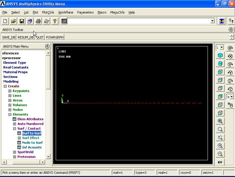
From Main Menu click Preprocessor - Modeling - Create - Elements - Surf/Contact - Surf to Surf. Mesh Free Surfaces window appears. From Surface element form list select Bottom surface and click OK.

Mesh Free Surfaces window appears. Select Box option from window and draw a rectangle to select the nodes. Click OK.

To view the whole model, from Menu click Select - Everything. The from Menu click Plot Multi-Plots.

Now we need to assign the Target elements to the top edge of the smooth surface. From Menu click Select - Entities - Select Entities window appears. From first list select Lines and from second list select By Num/Pick then from the list select From Full and click OK.

Select Lines window appears. Pick the top edge and click OK.

From Menu click Plot - Lines.

From Menu click Select - Entities - Select Entities window appears. From first list select Nodes and from second list select Attached to and from bottom lists select Lines, all and Reselect then click OK.

From Menu click Plot - Nodes.

Again from Menu click Select - Entities. Select Entities window appears. From first list select Nodes and from second list select By Num/Pick and from bottom list select Reselect. Click OK.

Reselect nodes window appears. Select Box and pick the nodes by drawing a rectangle as shown in figure. Click OK.

From Menu click Plot - Nodes.

Now we must assign the contact elements to the selected nodes. From Main Menu click Preprocessor - Modeling - Create - Elements - Elem Attributes. Element Attributes window appears. From Element type number list select TARGE169. Click OK.

From Main Menu click Preprocessor - Modeling - Create - Elements - Surf/Contact - Surf to Surf. Mesh Free Surfaces window appears. From Surface element form list select Top surface and click OK.

Mesh Free Surfaces window appears. Select Box option from window and select the nodes. Click OK.

From Menu click Select - Everything. Then from Menu click Plot - Elements.

5). To apply Boundary Conditions, from Main Menu click Preprocessor - Loads - Define Loads - Apply - Structural - Displacement - On Lines. Apply U, ROT on Lines window appears. Pick the left side edges of the circle and rectangle as shown in figure. Click OK.

Apply U, ROT on Lines window appears. From list select UX and click OK.

From Main Menu click Preprocessor - Loads - Define Loads - Apply - Structural - Displacement - On Lines. Apply U, ROT on Lines window appears. Pick the bottom edge as shown in figure. Click OK.

Apply U, ROT on Lines window appears. From list select UY and click OK.

6). To apply Loading, from Main Menu click Preprocessor - Loads - Define Loads - Apply - Structural - Pressure - On Lines. Apply PRES on Lines window appears. Pick the top edge of the circle and click OK.

Apply PRES on Lines window appears. In Load PRES value box enter 1 MPa and click OK.

===========================================================
Solution Stage:
From Main Menu click Solution - Solve - Current LS. Click OK to start solution. Close the window.
 =========================================================
Post Processing Stage:
From Main Menu click General Postproc - Plot Results - Contour Plot - Nodal Solu. Contour Nodal Solution Data window appears. Click Stress - Y-Component of stress. Click OK.


Again from Main Menu click General Postproc - Plot Results - Contour Plot - Nodal Solu. Contour Nodal Solution Data window appears. Click Stress - Y-Component of stress then select True Scale option from Scale Factor list. Click OK.


XY Shear stress:

Von Mises stress:
 ==========================================================
==========================================================


Apply U, ROT on Areas window appears. From list select UY and click OK.

7). To apply Load on top surface of the wheel, from Main Menu click Preprocessor - Loads - Define Loads - Apply - Structural - Pressure - On Areas. Apply PRES on Areas window appears. Pick the top surfcae of the cylinder and click OK.

Apply PRES on Areas window appears. In Load PRES value box enter 0.5e6MPa and click OK.

===========================================================
Solution Stage:
From Main Menu click Solution - Solve - Current LS. Click OK to start solution. Then close the window.

===========================================================
Post Processing Stage:
From Main Menu click General Postproc - Plot Results - Contour Plot - Nodal Solu. Contour Nodal Solution Data window appears. From list select Stress - Y-Component of stress. Click OK.


From Contour Nodal Solution Data window, select True Scale option for Scale Factor and click OK.


Von Mises stress:


1). To define Element Types, from Main Menu click Preprocessor - Element Type - Add/Edit/Delete. Element Types window appears. Click on Add button. Library of Element Types window appears. From left column select Solid and from right column select 8node 82 and click OK.

PLANE82 is added to the Element Types window.

Click on Options button. PLANE82 element type options window appears. From Element behavior list select Plane Strain and click OK.

NOTE: In contact stress problems, besides the whole geometry element (PLANE82), two other different elements of Surface and Target for meshing the contact region, must be defined. Therefore, again from Element Types window click on Add button. Library of Element Types window appears. From left column select Contact and from right column select 2D target 169. Click OK.

Again from Element Types window click on Add button. Library of Element Types window appears. From left column select Contact and from right column select 3 nd surf 172 and click OK.

Three elements (PLANE82, TARGE169, CONTA172) are added to the Element Types window. Close the window.

2). To define Material Properties, from Main Menu click Preprocessor - Material Props - Material Models. Define Material Model Behavior window appears. Click Structural - Linear - Elastic - Isotropic. Enter EX = 2.1e5 and PRXY = 0.3 and click OK.

3). To create the Geometry, from Main Menu click Preprocessor - Modeling - Create - Areas - Rectangle - By 2 Corners. Rectangle by 2 Corners window appears. Enter X = 0, Y = 0, Width = 500, and Height = -500 and click OK.


To create the quarter of the circle, from Main Menu click Preprocessor - Modeling - Create - Areas - Circle - Partial Annulus. Part Annular Circ Area window appears. Enter X = 0, Y = 500, Rad-1 = 500, Theta-1 = -90, Rad-2 = 500, and Theta-2 = 0 and click OK.


To connect these two geometries physically, from Main Menu click Preprocessor - Modeling - Operate - Booleans - Glue - Areas. Glue Areas window appears. Pick both the areas and click OK.

4). To Mesh the model, from Main Menu click Preprocessor - Meshing - Size Cntrls - ManualSize - Lines - Picked Lines. Then pick two lines as shown in the figure and click OK.

Element Sizes on Picked Lines window appears. In No. of element divisions box enter 60 and then in Spacing ratio box enter 1/10 and click Apply.

Element Size on Picked Lines window appears. Pick the two lines as shown in figure and click OK.

Element Sizes on Picked Lines window appears. In No. of element divisions box enter 60 and then in Spacing ratio box enter 10 and click Apply.

Element Size on Picked Lines window appears. Pick the two lines as shown in figure and click OK.

Element Sizes on Picked Lines window appears. In No. of element divisions box enter 40 and then in Spacing ratio box enter 10 and click Apply.

Element Size on Picked Lines window appears. Pick the line as shown in figure and click OK.

Element Sizes on Picked Lines window appears. In No. of element divisions box enter 40 and then in Spacing ratio box enter 1/10 and click OK.

From Main Menu click Preprocessor - Meshing - Mesh - Areas - Free. Mesh Areas window appears. Pick all the areas and click OK.


In next stage, the model will be meshed with surface and target element as well. First we need to select the nodes on the arc section in contact with the surface. From Menu click Select - Entities. Select Entities window appears. From the first list select Lines and from the second list select By Num/Pick then click OK.

Select Lines window appears. Select the arc and click OK.

From Menu click Plot - Lines. The selected line is displayed.

Again from Menu click Select - Entities. Select Entities window appears. From the first list select Nodes and from the second list select Attached to. Then from bottom lists select Lines, all and Reselect option. Click OK.

From Menu click Plot - Nodes. The selected nodes are displayed.

To select the nodes near the contact area, from Menu click Select - Entities. Select Entities window appears. From first list select Nodes and from second list select By Num/Pick. Then from list select Reselect option and click OK.

Reselect nodes window appears. From window select Box and draw a box to select the contact area nodes. Click OK.


Now we must assign the contact elements to the selected nodes. From Main Menu click Preprocessor - Modeling - Create - Elements - Elem Attributes. Element Attributes window appears. From Element type number list select CONTA172. Click OK.

From Main Menu click Preprocessor - Modeling - Create - Elements - Surf/Contact - Surf to Surf. Mesh Free Surfaces window appears. From Surface element form list select Bottom surface and click OK.

Mesh Free Surfaces window appears. Select Box option from window and draw a rectangle to select the nodes. Click OK.

To view the whole model, from Menu click Select - Everything. The from Menu click Plot Multi-Plots.

Now we need to assign the Target elements to the top edge of the smooth surface. From Menu click Select - Entities - Select Entities window appears. From first list select Lines and from second list select By Num/Pick then from the list select From Full and click OK.

Select Lines window appears. Pick the top edge and click OK.

From Menu click Plot - Lines.
From Menu click Select - Entities - Select Entities window appears. From first list select Nodes and from second list select Attached to and from bottom lists select Lines, all and Reselect then click OK.

From Menu click Plot - Nodes.

Again from Menu click Select - Entities. Select Entities window appears. From first list select Nodes and from second list select By Num/Pick and from bottom list select Reselect. Click OK.

Reselect nodes window appears. Select Box and pick the nodes by drawing a rectangle as shown in figure. Click OK.

From Menu click Plot - Nodes.

Now we must assign the contact elements to the selected nodes. From Main Menu click Preprocessor - Modeling - Create - Elements - Elem Attributes. Element Attributes window appears. From Element type number list select TARGE169. Click OK.

From Main Menu click Preprocessor - Modeling - Create - Elements - Surf/Contact - Surf to Surf. Mesh Free Surfaces window appears. From Surface element form list select Top surface and click OK.

Mesh Free Surfaces window appears. Select Box option from window and select the nodes. Click OK.

From Menu click Select - Everything. Then from Menu click Plot - Elements.

5). To apply Boundary Conditions, from Main Menu click Preprocessor - Loads - Define Loads - Apply - Structural - Displacement - On Lines. Apply U, ROT on Lines window appears. Pick the left side edges of the circle and rectangle as shown in figure. Click OK.

Apply U, ROT on Lines window appears. From list select UX and click OK.

From Main Menu click Preprocessor - Loads - Define Loads - Apply - Structural - Displacement - On Lines. Apply U, ROT on Lines window appears. Pick the bottom edge as shown in figure. Click OK.

Apply U, ROT on Lines window appears. From list select UY and click OK.

6). To apply Loading, from Main Menu click Preprocessor - Loads - Define Loads - Apply - Structural - Pressure - On Lines. Apply PRES on Lines window appears. Pick the top edge of the circle and click OK.

Apply PRES on Lines window appears. In Load PRES value box enter 1 MPa and click OK.

===========================================================
Solution Stage:
From Main Menu click Solution - Solve - Current LS. Click OK to start solution. Close the window.

Post Processing Stage:
From Main Menu click General Postproc - Plot Results - Contour Plot - Nodal Solu. Contour Nodal Solution Data window appears. Click Stress - Y-Component of stress. Click OK.


Again from Main Menu click General Postproc - Plot Results - Contour Plot - Nodal Solu. Contour Nodal Solution Data window appears. Click Stress - Y-Component of stress then select True Scale option from Scale Factor list. Click OK.


XY Shear stress:

Von Mises stress:

==========================================================
Contact Stress (3D):
The model is a simplified model of a train wheel on the rail. The material of both wheel and rail is Steel and the friction coefficient is 0.1. And a 0.5MPa pressure is applied through wheel. The aim is to find the contact stress between rail and wheel.
The model is a simplified model of a train wheel on the rail. The material of both wheel and rail is Steel and the friction coefficient is 0.1. And a 0.5MPa pressure is applied through wheel. The aim is to find the contact stress between rail and wheel.

1). To define the Element Type, from Main Menu click Preprocessor - Element Type - Add/Edit/Delete. Element Types window appears. Click on Add button. Library of Element Types window appears. From left column select Solid and from right column select Brick 8node 185. Click OK.

SOLID185 is added to the Element Types window. Close this window.

2). To define Material Properties, from Main Menu click Preprocessor - Material Props - Material Models. Define Material Model Behavior window appears. Click Structural - Linear - Elastic - Isotropic. Enter EX = 2.1e9 and PRXY = 0.3 and click OK.

3). To create the Geometry, from Main Menu click Preprocessor - Modeling - Create - Areas - Rectangle - By Dimensions. Create Rectangle by Dimensions window appears. Enter X1 = 0, X2 = 2cm, Y1 = -0.5, and Y2 = -2.5 and click OK.


From Main Menu click Preprocessor - Modeling - Create - Areas - Rectangle - By Dimensions. Create Rectangle by Dimensions window appears. Enter X1 = 1, X2 = 2cm, Y1 = -0.5, and Y2 = -1 and click Apply.

Again enter X1 = 0.5, X2 = 2cm, Y1 = -1, and Y2 = -1.5 and click OK.

3 rectangles are created.

To display the area numbers, from Menu click PlotCtrls - Numbering. Plot Numbering Controls window appears. Activate area numbers and click OK.


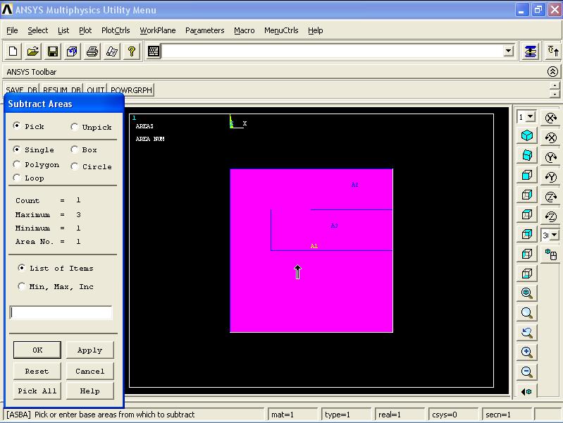
Now we need to remove area number 3 from number 1. From Main Menu click Preprocessor - Modeling - Operate - Booleans - Subtract - Areas. Subtract Areas window appears. Pick rectangle number 1 and click OK.

Subtract Areas window again appears. Pick rectangle number 3 and click OK.


Next we need to remove the rectangle number 2 from the main area. From Main Menu click Preprocessor - Modeling - Operate - Booleans - Subtract - Areas. Subtract Areas window appears. Pick the main area and click OK.

Subtract Areas window again appears. Pick the rectangle number 2 and click OK.


Before creating the second part (Wheel), we need to rotate the coordinate system 90 degree. From Menu click WorkPlane - Offset WP by Increments. Offset WP window appears. In XY, YZ, ZX Angles box enter 0,0,-90 and click OK.

From Main Menu click Preprocessor - Modeling - Create - Areas - Circle - By Dimensions. Circular Area by Dimensions window appears. Enter Outer radius = 0.5, Optional inner radius = 0, Starting angle = 270, Ending angle = 360 and click OK.


Now we need to return the coordinate system to its original position. From Menu click WorkPlane - Offset WP by Increments. Offset WP window appears. In XY, YZ, ZX Angles box enter 0,0,90 and click OK.

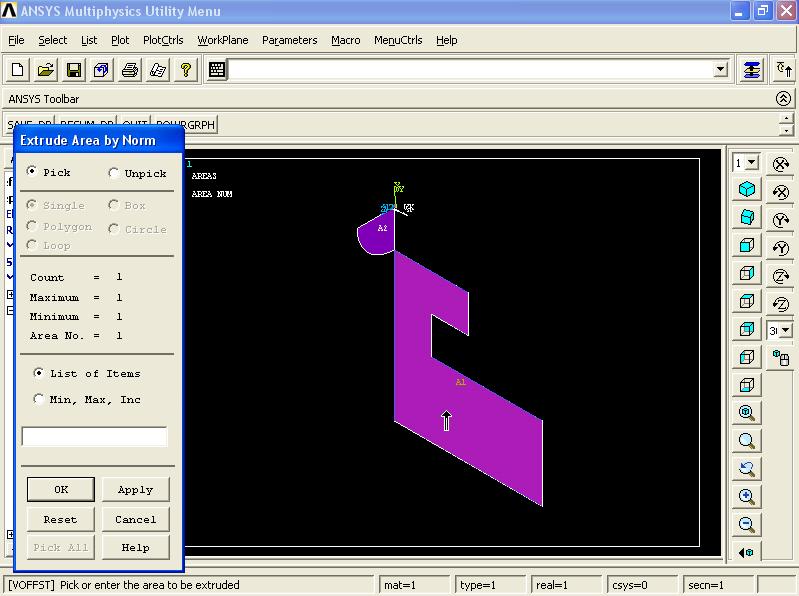
In next stage, the areas are extruded in the direction of normal to the areas. From Main Menu click Preprocessor - Modeling - Operate - Extrude - Areas - Along Normal. Extrude Area by Norm window appears. Pick the first area and click OK.

Extrude Area along Normal window appears. In Length of extrusion box enter 1cm and click OK.


Repeat the above process to create the second volume. From Main Menu click Preprocessor - Modeling - Operate - Extrude - Areas - Along Normal. Extrude Area by Norm window appears. Pick the second area and click OK.

Extrude Area along Normal window appears. In Length of extrusion box enter -1cm and click OK.


From Menu click Plot - Volumes. Then from Menu click PlotCtrls - Numbering. Plot Numbering Controls window appears. Deactivate Area numbers and activate Volume numbers. Click OK.


4). To Mesh the model, from Main Menu click Preprocessor - Meshing - Mesh Tool. Mesh Tool window appears. Click on Lines Set button.

Element Size on Picked Lines window appears. Pick the two lines on wheel as shown in the figure. Make sure the picked line is 31 and click OK. Again click OK to close Element Size on Picked Lines window.

Element Sizes on Picked Lines window appears. Note that both lines belong to the cylinder. In No. of element divisions box enter 30 and uncheck the SIZE, NDIV can be changed option. As shown in figure. Click OK.

Now repeat the above process for rail as well. From Main Menu click Preprocessor - Meshing - Mesh Tool. Mesh Tool window appears. Click on Lines Set button.

Element Size on Picked Lines window appears. Pick the two lines on rail as shown in the figure. Make sure the picked line is 2 and click OK. Again click OK to close Element Size on Picked Lines window.

Element Sizes on Picked Lines window appears. Note that both lines belong to the cylinder. In No. of element divisions box enter 30 and uncheck the SIZE, NDIV can be changed option. As shown in figure. Click OK.

In Mesh Tool window, from Mesh: list select Volumes. From Shape: select Hex and then Sweep. Then click on Sweep button.

Volume Sweeping window appears. Click on Pick All button.

The model is meshed.

From Menu click PlotCtrls - Style - Size and Shape. Size and Shape window appears. From Facets/element edge list select 2 facets/edge option. Click OK.

This cause the elements to be displayed better and properly.

5). To define the Surface Contacts and create the Contact Elements, from Main Menu click Preprocessor - Modeling - Create - Contact Pair. Contact Manager window appears.

Then from window click on Contact Wizard button.

Contact Wizard window appears. From Target Surface: select Areas and from Target Type: select Flexible. Then click on Pick Target button.

Select Areas for Target window appears. Pick the top surface of the rail as shown in the figure and click OK.

Contact Wizard window again appears. Then click on Next button.

In the next wizard window, from Contact Surface: select Areas and from Contact Element Type: select Surface-to-Surface the click on Pick Contact button.

Select Areas for Contact window appears. Then pick the bottom surface of the wheel as shown in the figure and click OK.

Click on Next button.

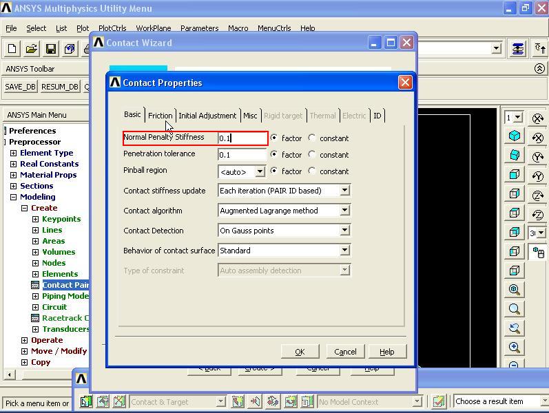
In next wizard window, uncheck the Include initial penetration option and in Coefficient of Friction enter 0.1 and click on Optional settings button.

Contact Properties window appears. In Basic tab, in Normal Penalty Stiffness box enter 0.1.

Then from Contact Properties window enter Friction tab. From Stiffness matrix list select Unsymmetric.

Then from Contact Properties window enter Initial Adjustment tab. And from Automatic contact adjustment list select Close gap. And click OK to close this window.

Contact Wizard window appears. Click on Create> button.

Then click on Finish button.

Close the Contact Manager window.


6). To apply Boundary Conditions, from Main Menu click Preprocessor - Loads - Define Loads - Apply - Structural - Displacement - On Areas. Apply U, ROT on Areas window appears. Pick the areas as shown in the figure. Click OK.

Apply U, ROT on Areas window appears. From list select UX and click OK.

From Main Menu click Preprocessor - Loads - Define Loads - Apply - Structural - Displacement - On Areas. Apply U, ROT on Areas window appears. Pick the areas as shown in the figure. Click OK.

Apply U, ROT on Areas window appears. From list select UZ and click OK.

Finally, from Main Menu click Preprocessor - Loads - Define Loads - Apply - Structural - Displacement - On Areas. Apply U, ROT on Areas window appears. Pick the bottom area of the rail as shown in the figure. Click OK.

SOLID185 is added to the Element Types window. Close this window.

2). To define Material Properties, from Main Menu click Preprocessor - Material Props - Material Models. Define Material Model Behavior window appears. Click Structural - Linear - Elastic - Isotropic. Enter EX = 2.1e9 and PRXY = 0.3 and click OK.

3). To create the Geometry, from Main Menu click Preprocessor - Modeling - Create - Areas - Rectangle - By Dimensions. Create Rectangle by Dimensions window appears. Enter X1 = 0, X2 = 2cm, Y1 = -0.5, and Y2 = -2.5 and click OK.


From Main Menu click Preprocessor - Modeling - Create - Areas - Rectangle - By Dimensions. Create Rectangle by Dimensions window appears. Enter X1 = 1, X2 = 2cm, Y1 = -0.5, and Y2 = -1 and click Apply.

Again enter X1 = 0.5, X2 = 2cm, Y1 = -1, and Y2 = -1.5 and click OK.

3 rectangles are created.


Now we need to remove area number 3 from number 1. From Main Menu click Preprocessor - Modeling - Operate - Booleans - Subtract - Areas. Subtract Areas window appears. Pick rectangle number 1 and click OK.
Subtract Areas window again appears. Pick rectangle number 3 and click OK.


Next we need to remove the rectangle number 2 from the main area. From Main Menu click Preprocessor - Modeling - Operate - Booleans - Subtract - Areas. Subtract Areas window appears. Pick the main area and click OK.

Subtract Areas window again appears. Pick the rectangle number 2 and click OK.


Before creating the second part (Wheel), we need to rotate the coordinate system 90 degree. From Menu click WorkPlane - Offset WP by Increments. Offset WP window appears. In XY, YZ, ZX Angles box enter 0,0,-90 and click OK.

From Main Menu click Preprocessor - Modeling - Create - Areas - Circle - By Dimensions. Circular Area by Dimensions window appears. Enter Outer radius = 0.5, Optional inner radius = 0, Starting angle = 270, Ending angle = 360 and click OK.


Now we need to return the coordinate system to its original position. From Menu click WorkPlane - Offset WP by Increments. Offset WP window appears. In XY, YZ, ZX Angles box enter 0,0,90 and click OK.

In next stage, the areas are extruded in the direction of normal to the areas. From Main Menu click Preprocessor - Modeling - Operate - Extrude - Areas - Along Normal. Extrude Area by Norm window appears. Pick the first area and click OK.
Extrude Area along Normal window appears. In Length of extrusion box enter 1cm and click OK.


Repeat the above process to create the second volume. From Main Menu click Preprocessor - Modeling - Operate - Extrude - Areas - Along Normal. Extrude Area by Norm window appears. Pick the second area and click OK.

Extrude Area along Normal window appears. In Length of extrusion box enter -1cm and click OK.


From Menu click Plot - Volumes. Then from Menu click PlotCtrls - Numbering. Plot Numbering Controls window appears. Deactivate Area numbers and activate Volume numbers. Click OK.


4). To Mesh the model, from Main Menu click Preprocessor - Meshing - Mesh Tool. Mesh Tool window appears. Click on Lines Set button.

Element Size on Picked Lines window appears. Pick the two lines on wheel as shown in the figure. Make sure the picked line is 31 and click OK. Again click OK to close Element Size on Picked Lines window.

Element Sizes on Picked Lines window appears. Note that both lines belong to the cylinder. In No. of element divisions box enter 30 and uncheck the SIZE, NDIV can be changed option. As shown in figure. Click OK.

Now repeat the above process for rail as well. From Main Menu click Preprocessor - Meshing - Mesh Tool. Mesh Tool window appears. Click on Lines Set button.

Element Size on Picked Lines window appears. Pick the two lines on rail as shown in the figure. Make sure the picked line is 2 and click OK. Again click OK to close Element Size on Picked Lines window.

Element Sizes on Picked Lines window appears. Note that both lines belong to the cylinder. In No. of element divisions box enter 30 and uncheck the SIZE, NDIV can be changed option. As shown in figure. Click OK.

In Mesh Tool window, from Mesh: list select Volumes. From Shape: select Hex and then Sweep. Then click on Sweep button.

Volume Sweeping window appears. Click on Pick All button.

The model is meshed.

From Menu click PlotCtrls - Style - Size and Shape. Size and Shape window appears. From Facets/element edge list select 2 facets/edge option. Click OK.

This cause the elements to be displayed better and properly.

5). To define the Surface Contacts and create the Contact Elements, from Main Menu click Preprocessor - Modeling - Create - Contact Pair. Contact Manager window appears.

Then from window click on Contact Wizard button.

Contact Wizard window appears. From Target Surface: select Areas and from Target Type: select Flexible. Then click on Pick Target button.

Select Areas for Target window appears. Pick the top surface of the rail as shown in the figure and click OK.

Contact Wizard window again appears. Then click on Next button.

In the next wizard window, from Contact Surface: select Areas and from Contact Element Type: select Surface-to-Surface the click on Pick Contact button.

Select Areas for Contact window appears. Then pick the bottom surface of the wheel as shown in the figure and click OK.

Click on Next button.

In next wizard window, uncheck the Include initial penetration option and in Coefficient of Friction enter 0.1 and click on Optional settings button.

Contact Properties window appears. In Basic tab, in Normal Penalty Stiffness box enter 0.1.
Then from Contact Properties window enter Friction tab. From Stiffness matrix list select Unsymmetric.

Then from Contact Properties window enter Initial Adjustment tab. And from Automatic contact adjustment list select Close gap. And click OK to close this window.

Contact Wizard window appears. Click on Create> button.

Then click on Finish button.

Close the Contact Manager window.


6). To apply Boundary Conditions, from Main Menu click Preprocessor - Loads - Define Loads - Apply - Structural - Displacement - On Areas. Apply U, ROT on Areas window appears. Pick the areas as shown in the figure. Click OK.

Apply U, ROT on Areas window appears. From list select UX and click OK.

From Main Menu click Preprocessor - Loads - Define Loads - Apply - Structural - Displacement - On Areas. Apply U, ROT on Areas window appears. Pick the areas as shown in the figure. Click OK.

Apply U, ROT on Areas window appears. From list select UZ and click OK.

Finally, from Main Menu click Preprocessor - Loads - Define Loads - Apply - Structural - Displacement - On Areas. Apply U, ROT on Areas window appears. Pick the bottom area of the rail as shown in the figure. Click OK.

Apply U, ROT on Areas window appears. From list select UY and click OK.

7). To apply Load on top surface of the wheel, from Main Menu click Preprocessor - Loads - Define Loads - Apply - Structural - Pressure - On Areas. Apply PRES on Areas window appears. Pick the top surfcae of the cylinder and click OK.

Apply PRES on Areas window appears. In Load PRES value box enter 0.5e6MPa and click OK.

===========================================================
Solution Stage:
From Main Menu click Solution - Solve - Current LS. Click OK to start solution. Then close the window.

===========================================================
Post Processing Stage:
From Main Menu click General Postproc - Plot Results - Contour Plot - Nodal Solu. Contour Nodal Solution Data window appears. From list select Stress - Y-Component of stress. Click OK.


From Contour Nodal Solution Data window, select True Scale option for Scale Factor and click OK.


Von Mises stress:

No comments:
Post a Comment